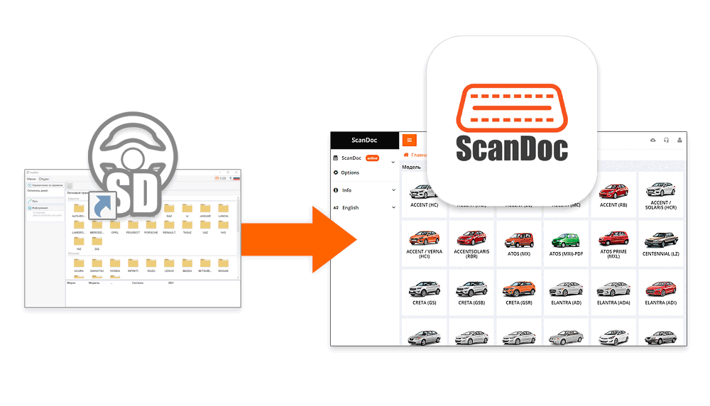
This video provides a detailed look at the ScanDoc program—a modern tool for vehicle diagnostics. You will learn about the interface layout, the functions available to the user, and how to use them to work faster and more efficiently.
Installation package for your chosen operating system (for example, for Windows OS, you need to download and install a file Setup.exe).
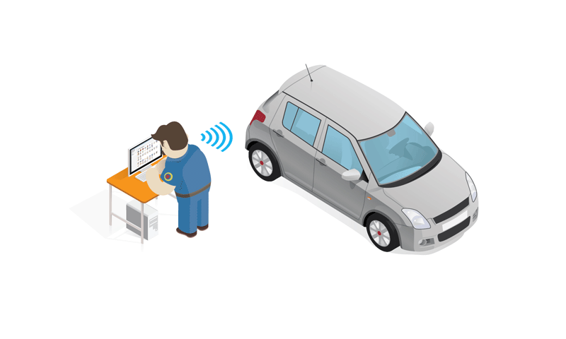
This version of the program works directly with the adapter via a WLAN network and does not require a permanent Internet connection.

To connect the ScanDoc scanner to a computer or phone via a WLAN network, you must enter the adapter password on WLAN .
The WLAN password is set in the adapter at the factory.
If your scanner has serial number s/n: 01230, then the WLAN connection will be named S1230 , and the password for the WLAN connection with the adapter will be scandoc1230 .
Change the password (Network name (SSID)) to the WLAN connection to the scanner
Install the software, in accordance with the type and bit depth of your operating system, from the manufacturer's website: quantexlab.com/en/download.html.
ScanDoc for Android (minimum version 6) can be downloaded from the official Google Play store.
The ScanDoc program for iOs (minimum version 10) can be downloaded from the official App Store.
Launch the new ScanDoc program on your device (computer, laptop, tablet, phone) using the shortcut on the desktop. (The operating system may ask for permission to access the Internet, allow access.)
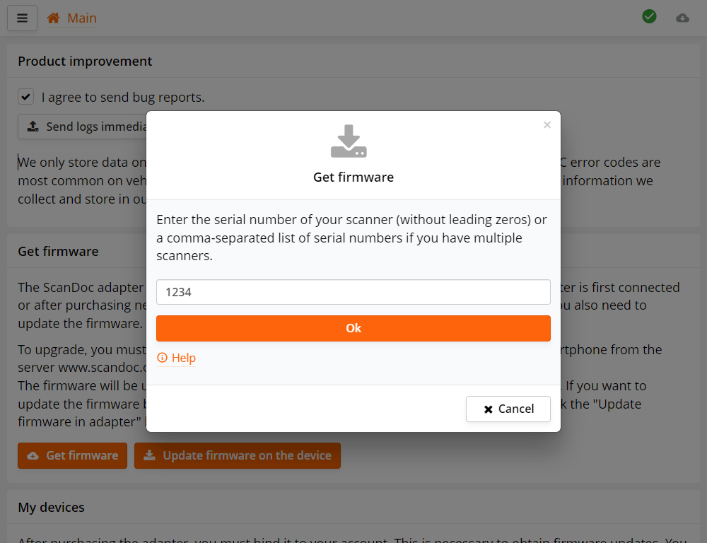
The first time you run the program, a form for entering serial numbers will appear, enter the serial number of your scanner.
If your scanner has serial number s/n: 01230, enter the number 1230.
If you have multiple scanners, enter their serial numbers separated by commas, for example: 25478, 1234..
Next, the program will automatically download firmware files from the Internet for your scanner.
This is only necessary if you were working with an old program and now switch to a new program or buy a new scanner.
If you worked in a new program, then skip this step.


If the adapter did not update for some reason, then you can exit the boot mode by turning off and then turning on the power of the device.

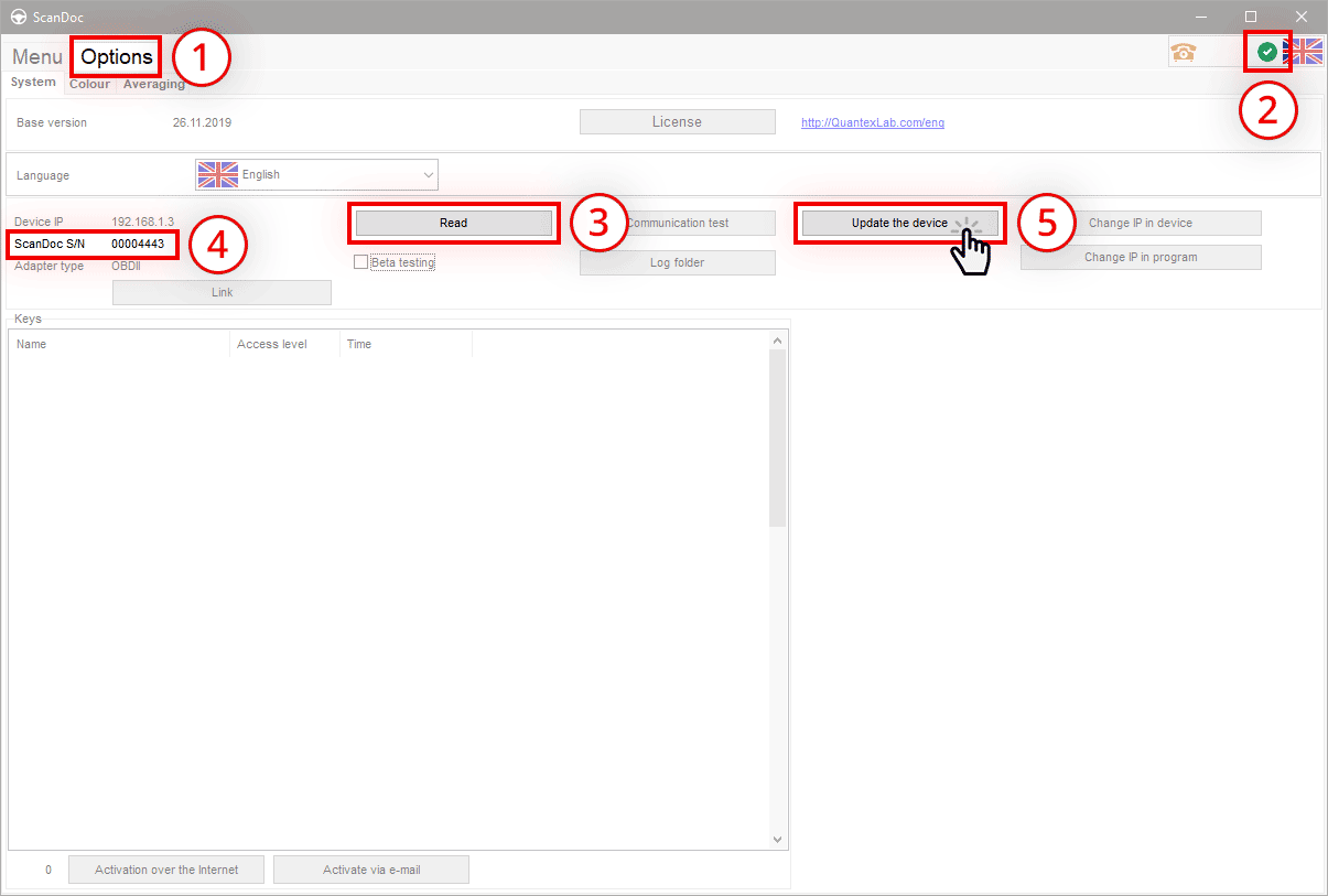
In the program, click the Update the firmware on the device button
The program will be stored in the scanner. The device is now ready.
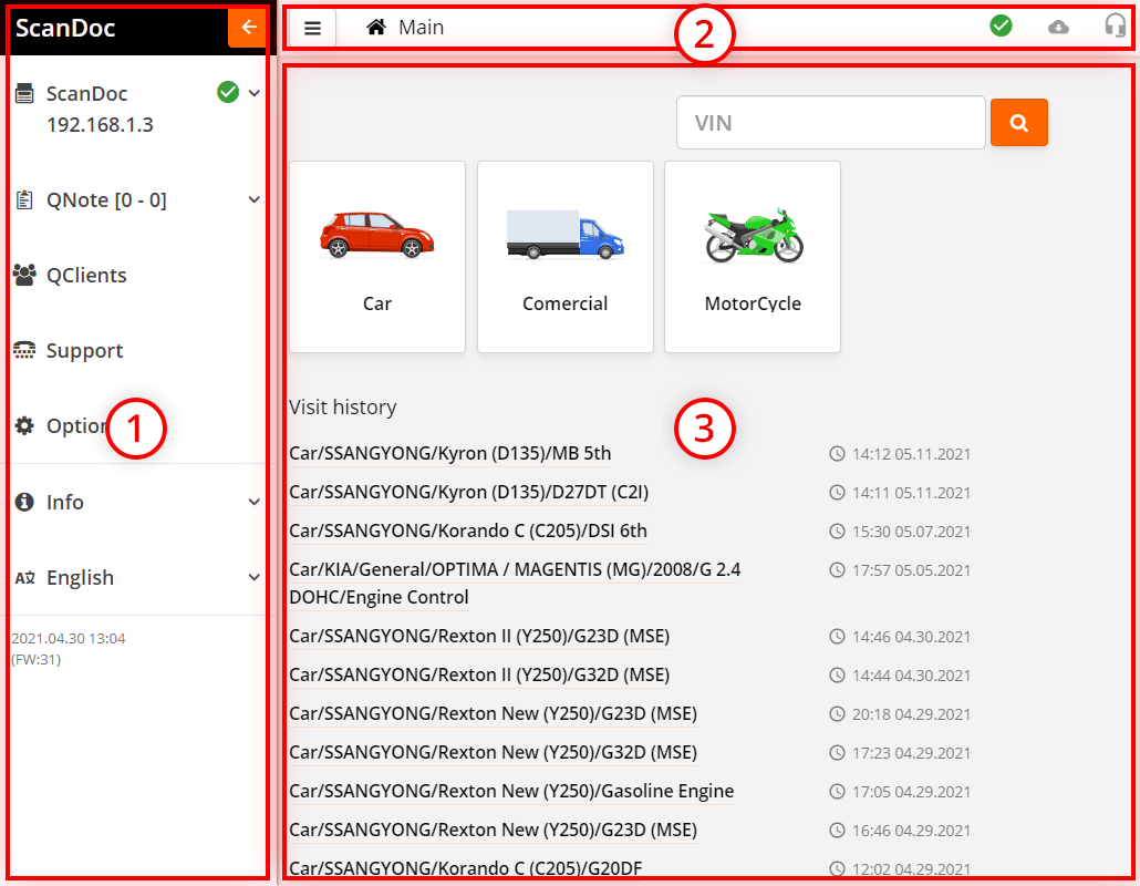
The program window is conditionally divided into 3 working zones.
| Side menu open button. | |
| Path
For example:
Main / Car / SSANGYONG / Actyon sport II (Q150) |
|
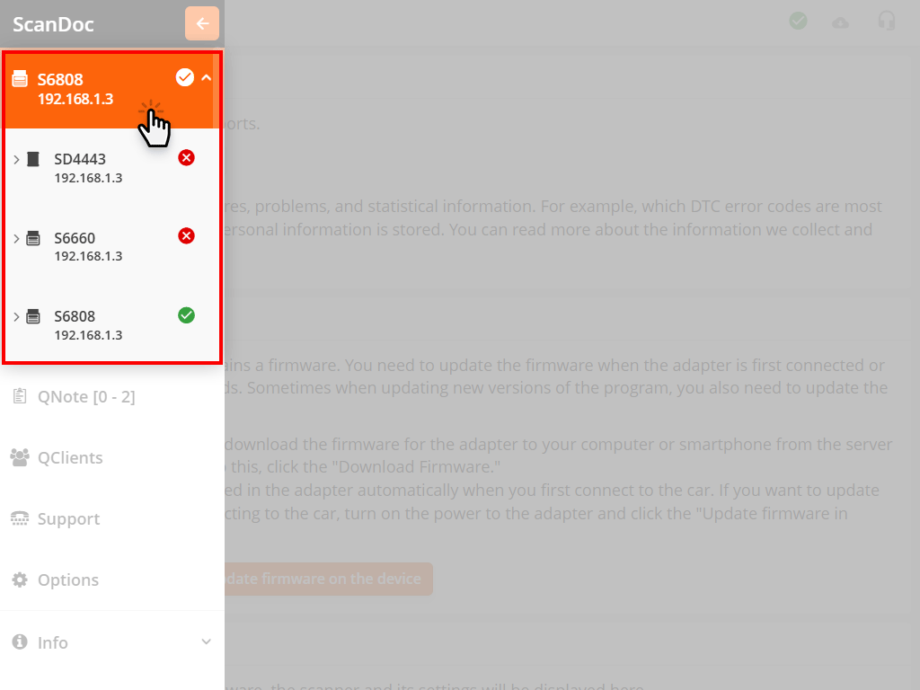
| Indicator of the quality of communication between the program and the scanner:
- stable connection
- connection is unstable - no connection with the scanner |
|
| Link to the download page for the new program. | |
| Creation of a request for technical support. |
You can zoom in or out using the browser.
For operating systems based on Windows, press the keyboard shortcut:
For operating systems based on macOS, press the keyboard shortcut:
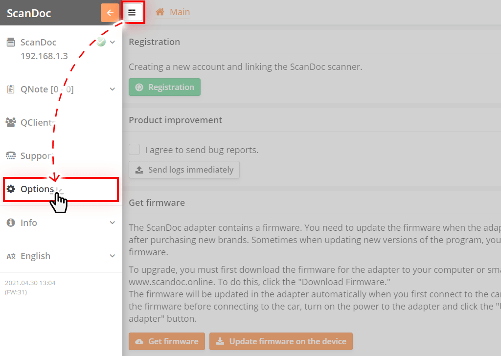
Run the program installed on your computer or mobile device.
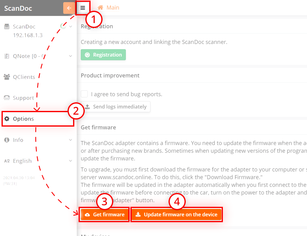
Click the button at the top of the window, an additional side menu will appear.
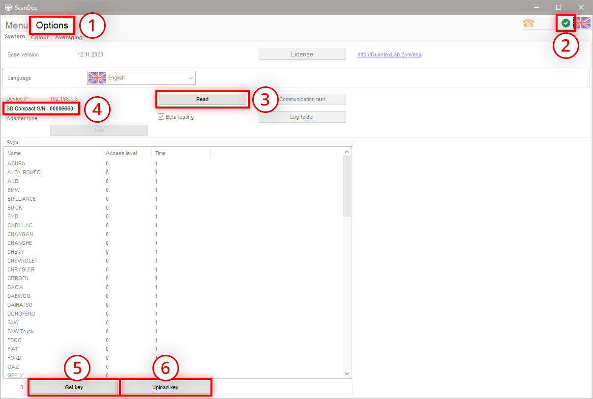
Click the "Options" button in the side menu, you will be taken to the program settings window.
Consider the items in this window.
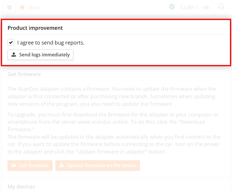
If "I agree to send bug reports" is checked, the program will send internal error reports automatically.
If you have disabled automatic sending of error reports, you can send all accumulated information manually by pressing the Send logs immediately button (internet access is required).
We only store data on malfunctions and problems, as well as statistical information. For example, which error codes occur most frequently on which vehicles. No personal information is stored. You can read more about the information we collect and store in our privacy policy.
For more information about working with tech support, see page Contacting technical support
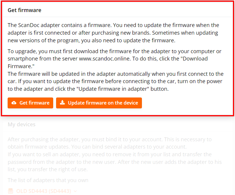
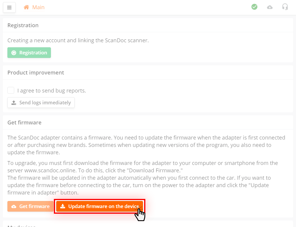
The Get firmware button downloads the firmware for your scanner from the server (internet access required).
The Update firmware on the device button writes firmware to the adapter (requires connection to the scanner's WLAN network).
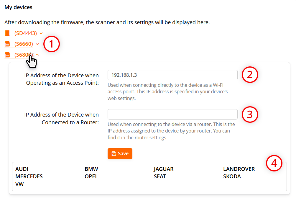
After successfully downloading the firmware, you can see here:
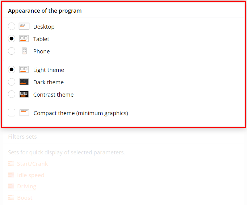
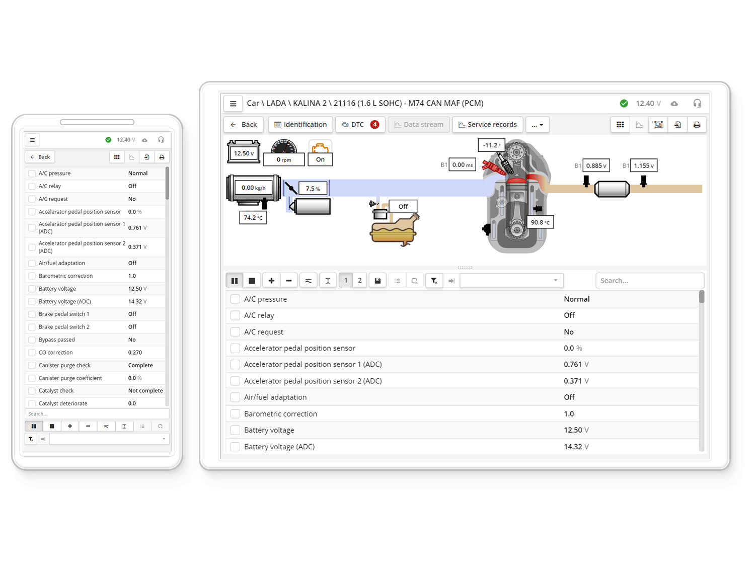
You can select different options for displaying the interface
| Desktop | - interface optimized for computer operation, smaller controls, more information on the screen |
| Tablet | - interface with enlarged controls for easy finger operation, less information on the screen |
| Phone | - interface is optimized for smartphones |
| Light theme | - standard light interface theme on white background |
| Dark theme | - the dark theme of the interface uses less battery power on your device |
| Contrast theme | - dark interface theme with contrasting controls |
| Compact theme | - interface with minimal graphics (car images will not be displayed) |
The modules are “attached” to the serial number of the adapter and cannot be transferred to another scanner.
After purchasing a new brand from a dealer, you need to update the firmware on the device. If several scanners are attached to your account, then the firmware is downloaded for all your adapters, although new modules may not be open on all scanners.
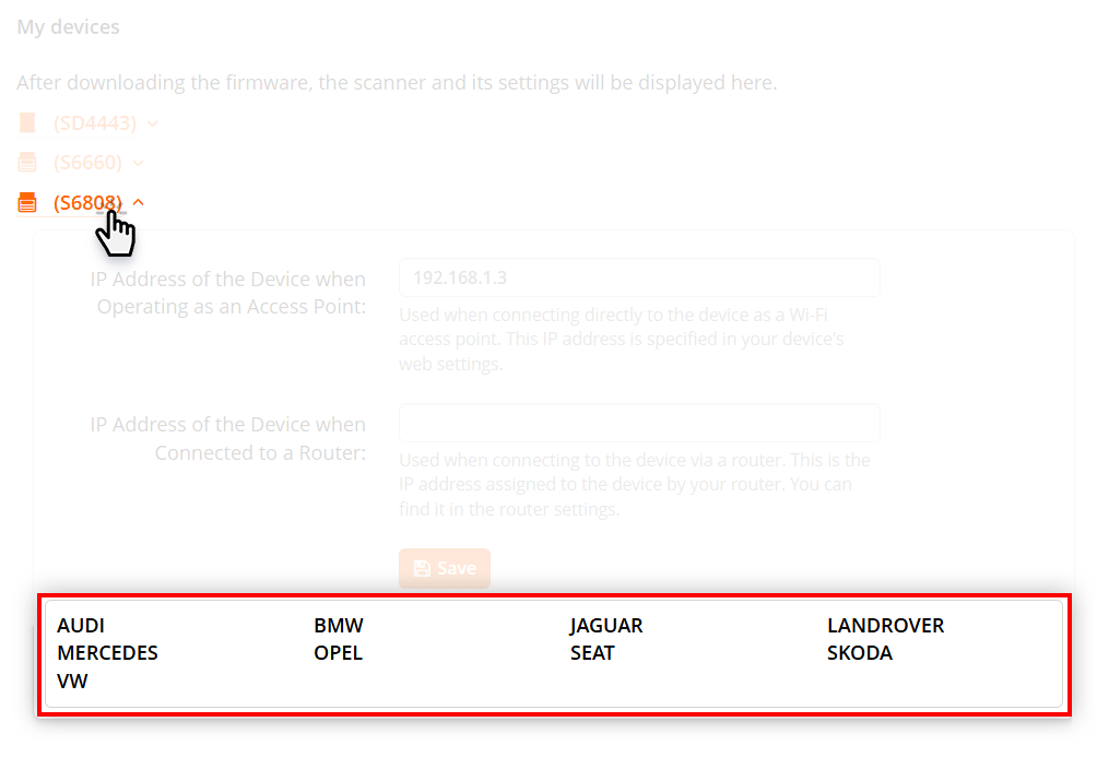
To see the list of purchased brands, in the My devices section, click on the adapter serial number link.
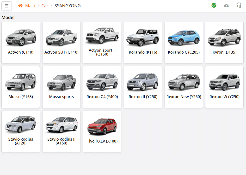
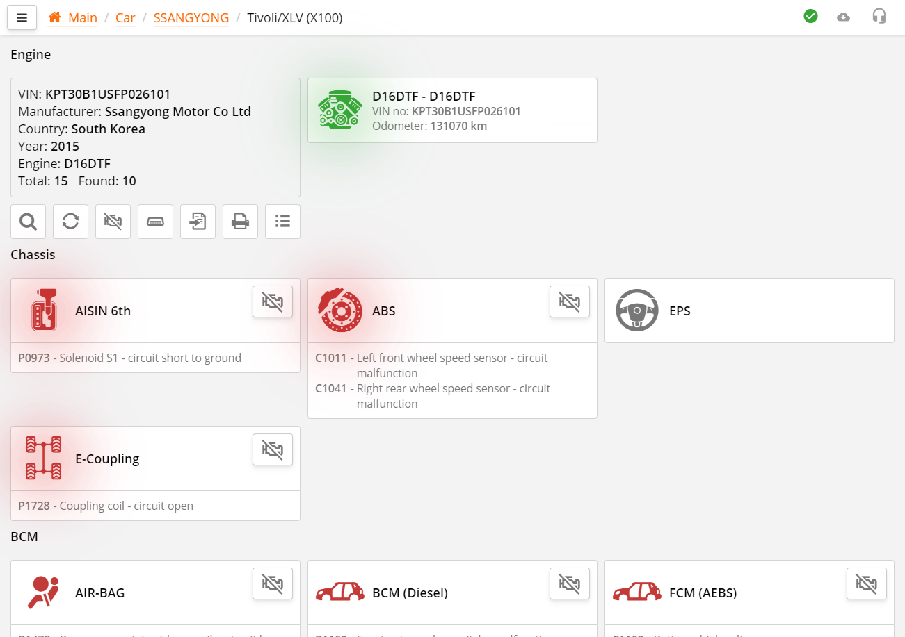
You can select the ECU block manually. Left-click on a tile, for example, make, model, vehicle ECU.
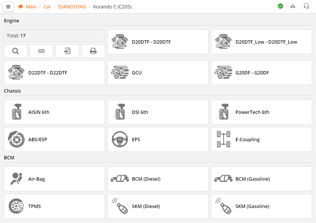
The system selection window is divided into groups for clarity: engine, chassis, body and multimedia.
You can quickly find the desired ECU unit.
You can also see the car card here.
Here is information about the car, the maximum number of ECU units.
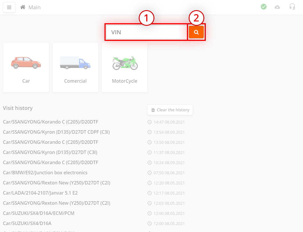
If you got to this window by entering the VIN code on the main page, then the card will also show additional information.
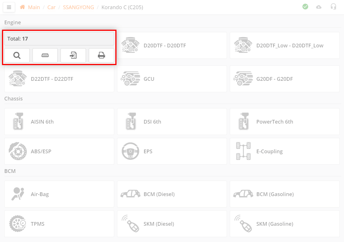
Function buttons that apply to the entire vehicle, not to any specific ECU.
Let's take a closer look at the functions.
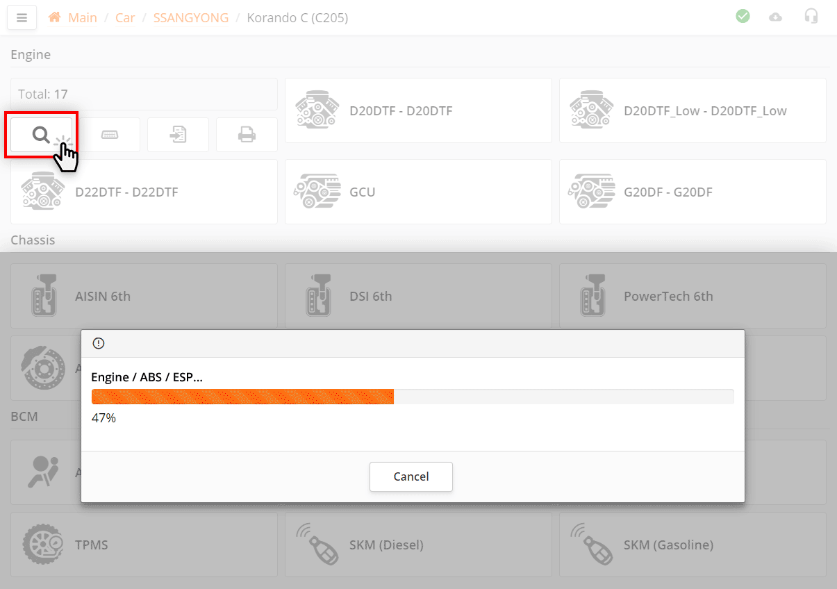
During automatic search, the program tries to connect to all possible ECUs for this car. If the ECU is present, the program reads the identification, codes and DTCs from it.
Sometimes, during auto search, the program may ask you to clarify additional information about the car, for example, what type of air conditioner is installed on the car.
The more ECUs that can be present in the car and the slower the communication protocols with them, the longer the automatic search takes.
Blocks of the ECU with which the program could not communicate will be hidden.
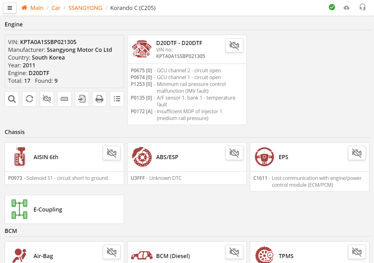
You will see a list of found ECU blocks for your car and primary information for analysis.
If the VIN number was read during autosearch or a search was performed by the VIN number of the car, then the program automatically remembers the list of found ECU blocks and saves it to itself. The next time you search for the VIN of the same vehicle, the program will not show the maximum list of ECUs, but the finished search result.
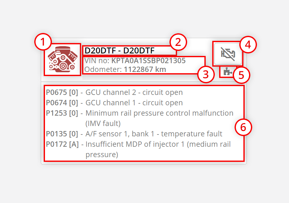
Graphically, ECU blocks are presented in the form of tiles, which consist of:
The ECU icon may have several colors depending on the test results:
This is done in order to focus attention on problematic ECU blocks.
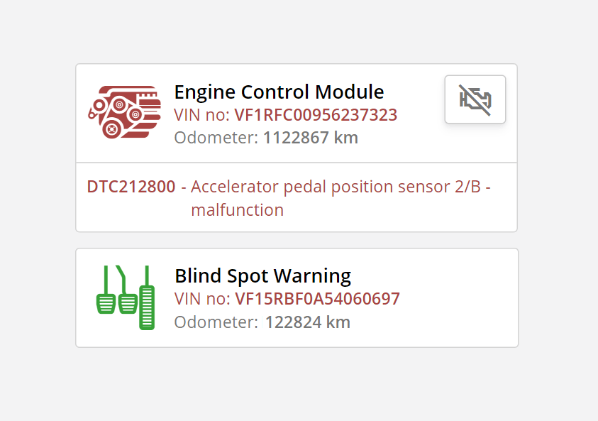
During autosearch, the program compares VIN numbers from ECU blocks and, if they do not match, then the VIN number is highlighted in red.
The program does not compare mileage, because mileage may vary slightly in different ECU units.
If the DTC has the status "active" or "current" then it is highlighted in red, otherwise it is highlighted in gray.
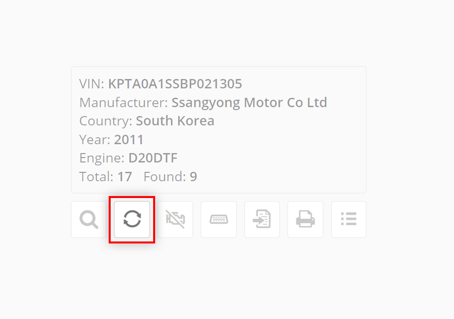
The " update" function differs from autosearch in that it does not try to contact all possible ECUs, but uses a list that was previously prepared by autosearch.
This saves time if it is known for sure that the number of ECUs in the car has not changed since the last visit.
For example: You connected to the car for the first time, performed auto search, saw DTCs, connected to the desired ECU, performed diagnostics. Now you need to put aside the scanner and repair the car. After the repair, you need to diagnose the car again. It makes no sense to re-search for all possible blocks.
To perform a quick update of information on ECU blocks, press the button.
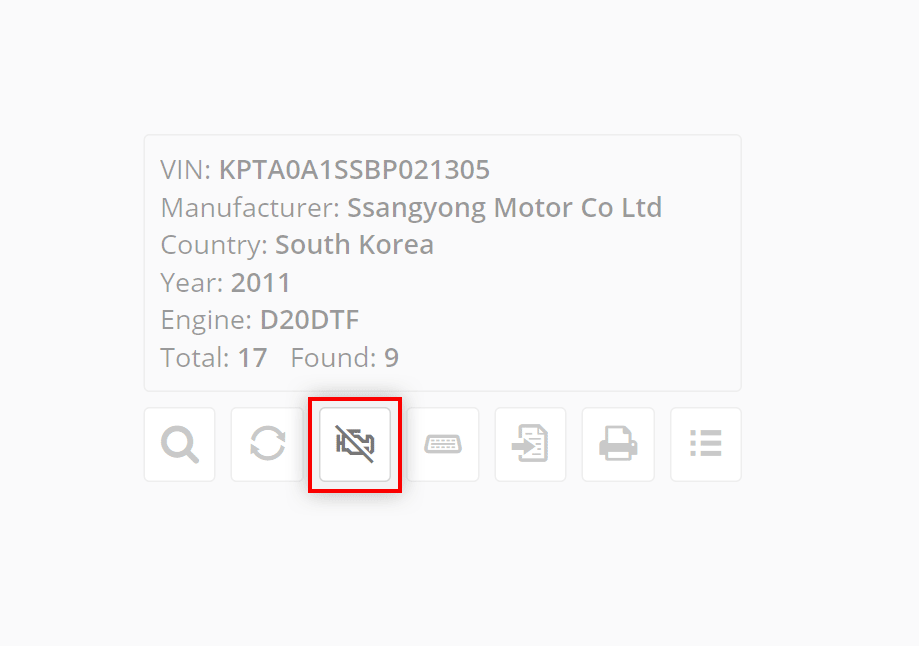
The button clears DTC errors in all found blocks.
Usually used to quickly erase DTCs in all ECUs of the car, without having to go into each ECU individually.
Press it, then reread the ECU blocks with the button to control.
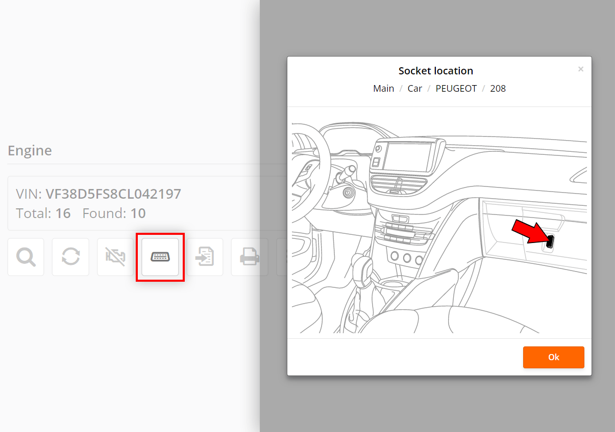
If you press the button, you will see the location of the diagnostic connector in the selected vehicle.
Sometimes the OBD-II connector may be in an unexpected place, such as in the glove compartment.
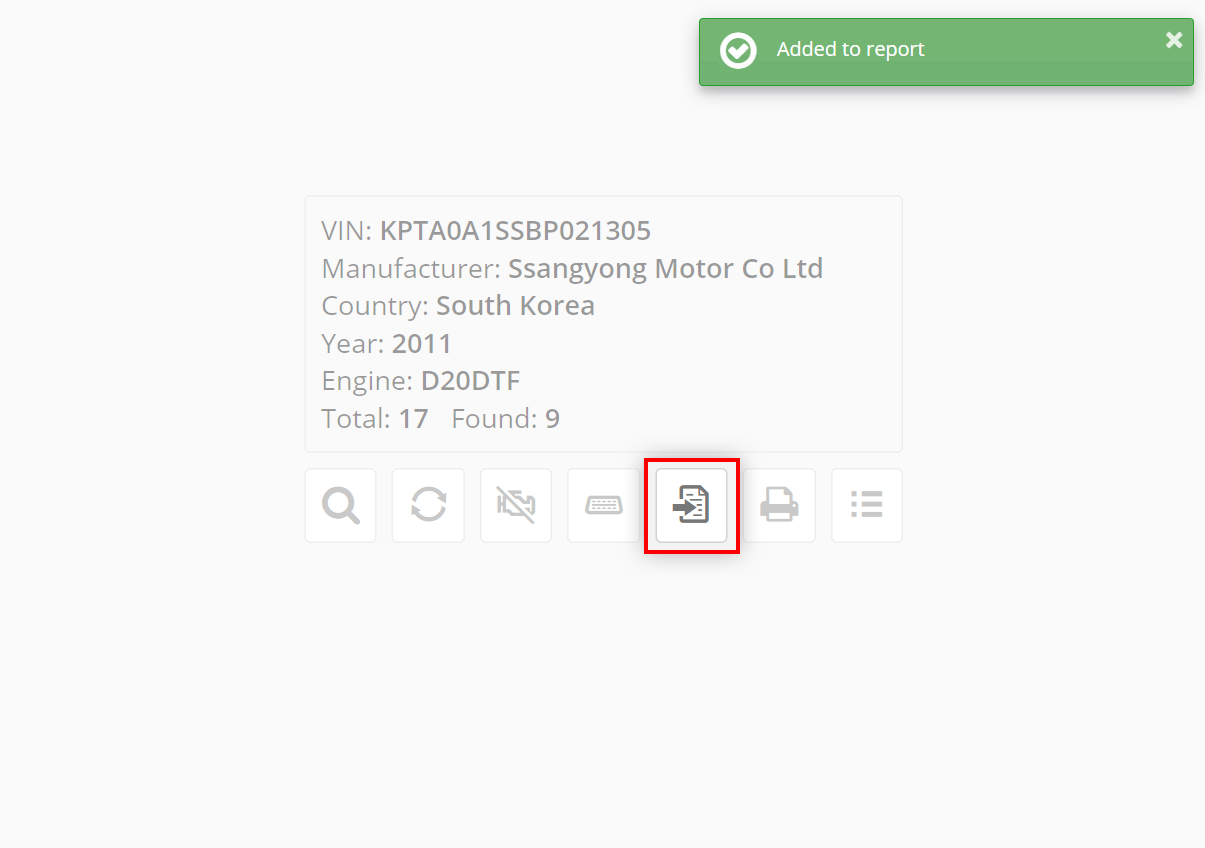
Using the button , you can save the auto-search data in the QClients accounting program for later analysis, saving or printing.
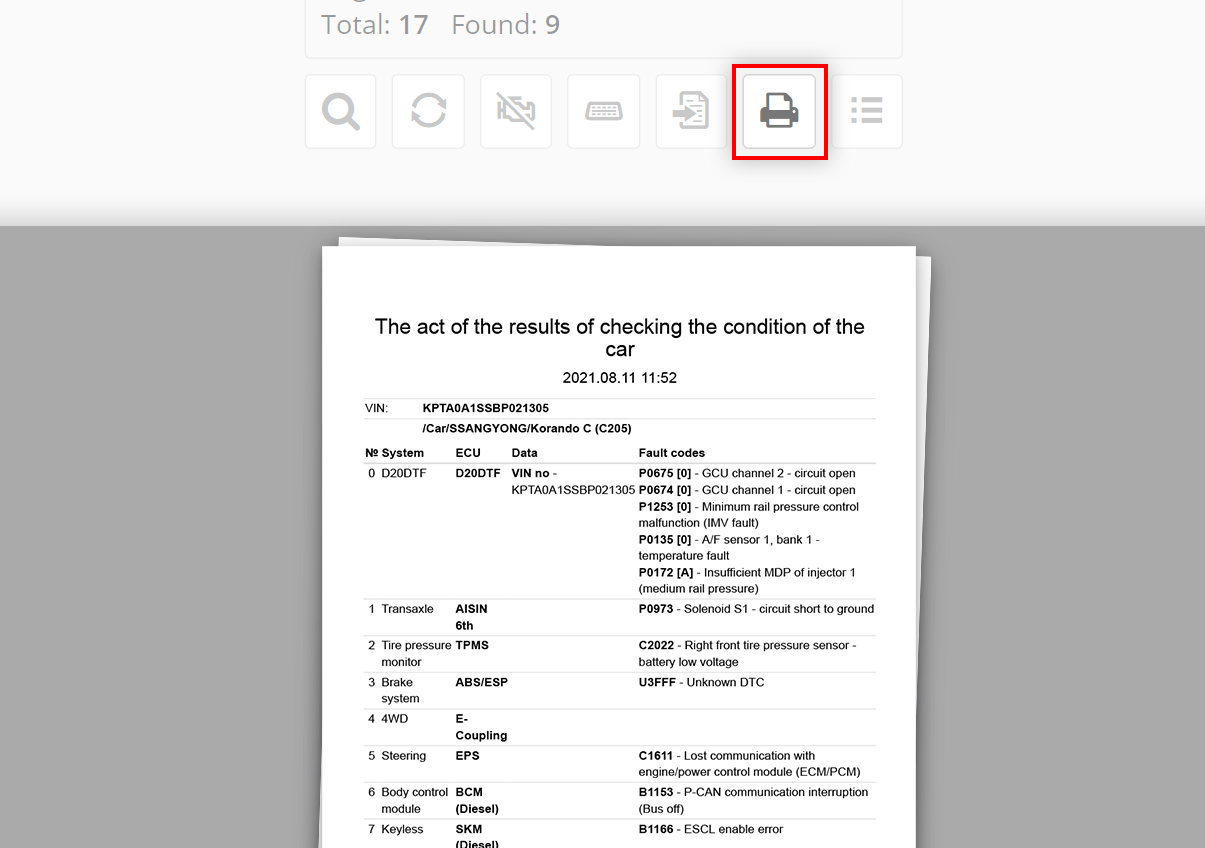
Press the button , the program will send the results of the current autosearch to print.
Quick Print is useful when you want to quickly print out a list of ECUs with DTCs and do not need to save the auto search data.
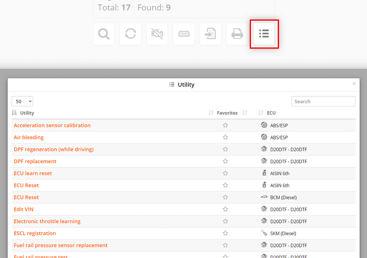
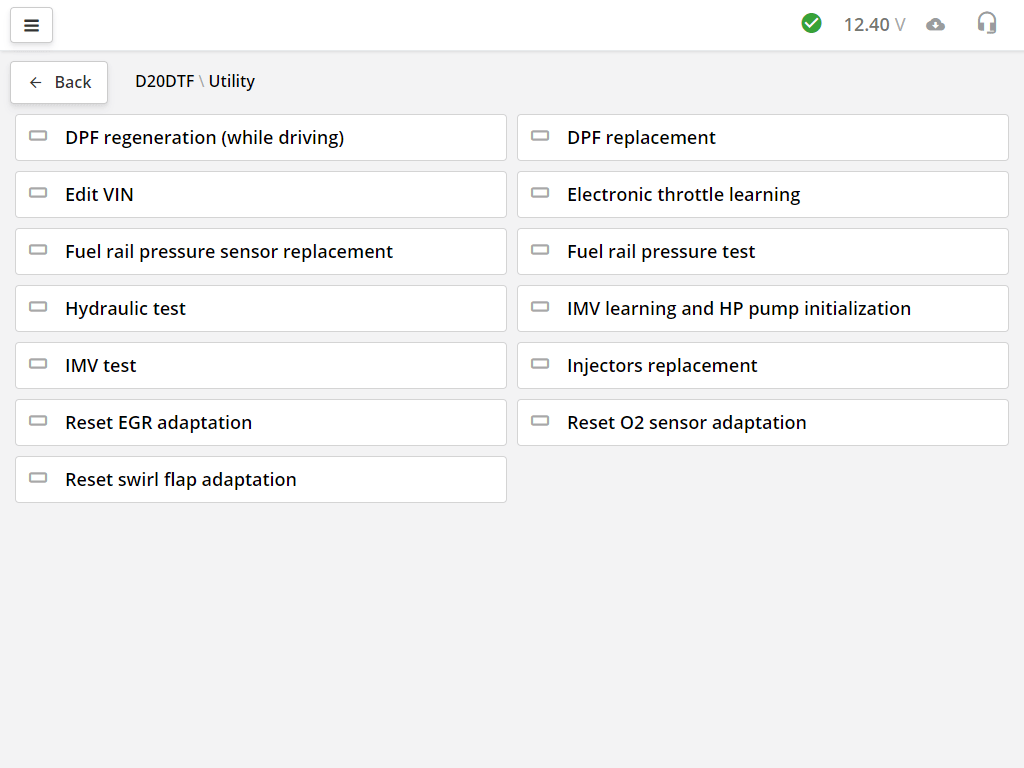
Click on the button , the program will show a list of all available utilities in the car.
To run a utility, click on its name.
This speeds up the work, since you do not need to look for which block contains the required utility. For example, the steering sensor calibration may be in the power steering unit, or it may be in the ABS unit.
Here you see the actual list of utilities that are present in this car, not a list of all possible utilities. This list will also be stored in the program under the vehicle's VIN number. The same car model with the same engines may have different configurations and the software in the ECU units may also support a different list of utilities.
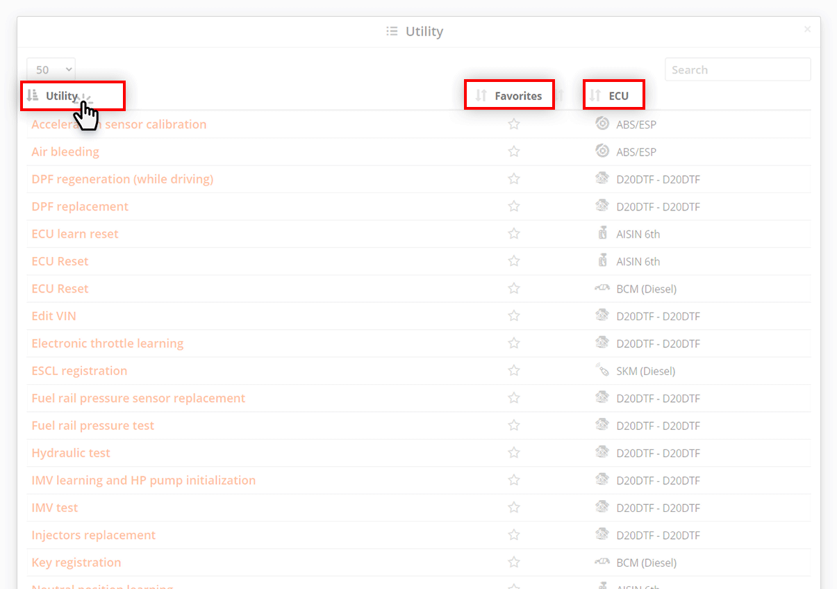
The list of utilities can be sorted by name, favorite utilities or by the system in which it is located. To sort, click on the table column heading.
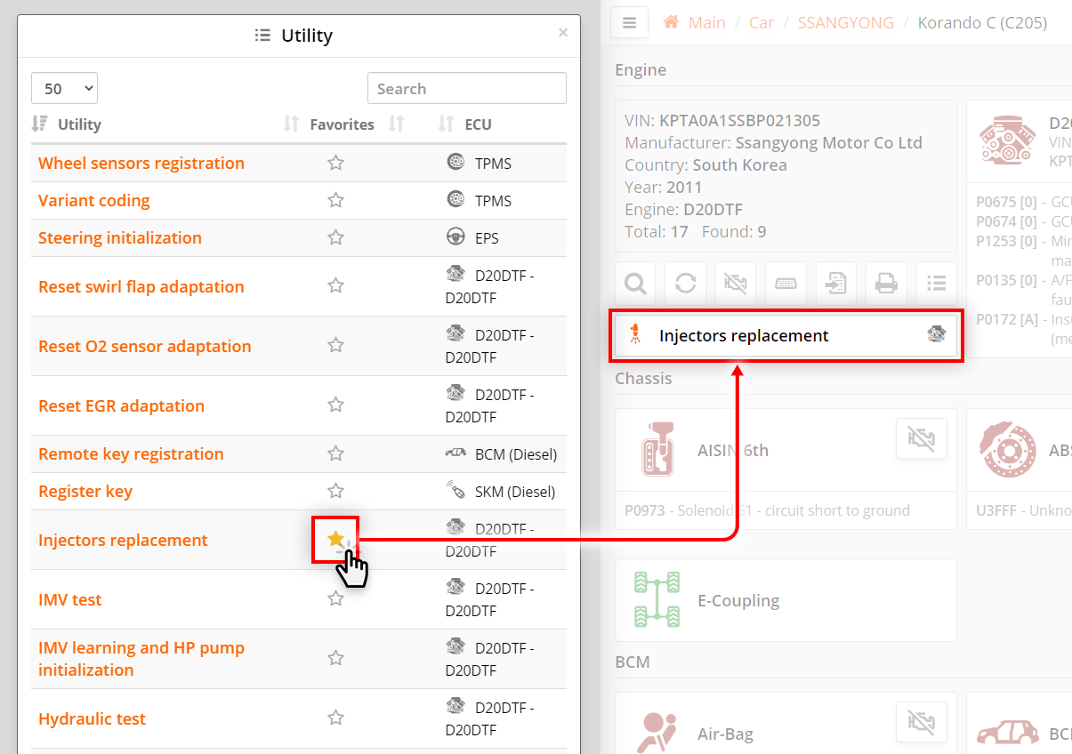
If you click on the star icon in the list of utilities, the utility will be added to the list of favorites. In this case, it will appear on the auto search page under the car card. Now the utility can be launched from the autosearch window.
If a utility with the same name is found in another car, it will immediately be displayed on the auto search page.
Clicking the star icon again removes the utility from the list of favorites and from the autosearch page.
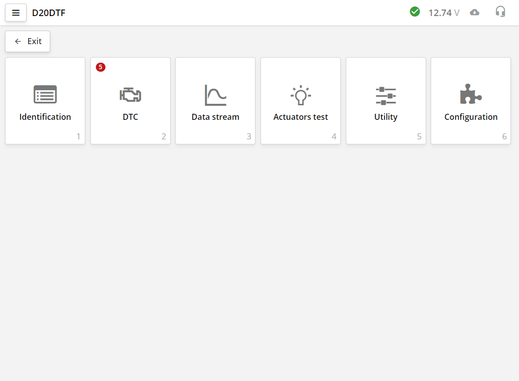
After communication with the electronic control unit (ECU) is established, the program will show the tabs of the diagnostic module.
In different ECU blocks there can be a different number of bookmarks.
The DTC tab shows the number of errors at once.
Depending on the type of ECU or diagnostic protocol, it may take from 0.5 to 15 seconds to start working with the ECU. Some ECUs require more time. This may be due both to the peculiarities of the diagnostic protocol itself, and to the reading of the vehicle configuration by the scanner.
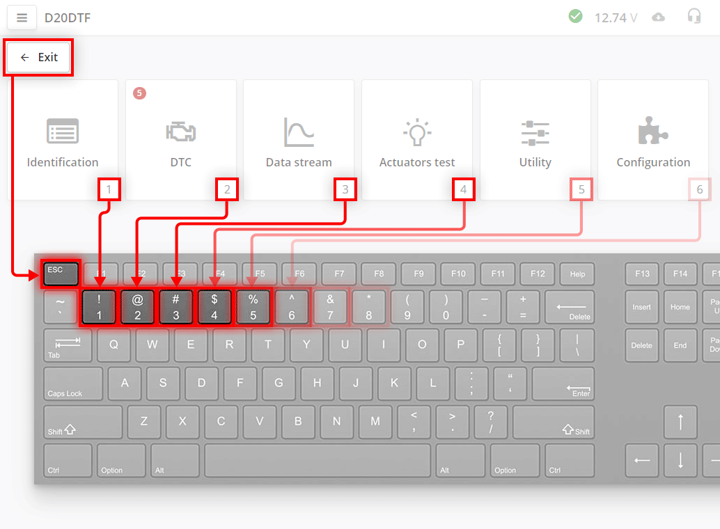
For quick access to bookmarks, access is provided by the keys on the keyboard.
The Esc button on the keyboard corresponds to the Exit button in the program.
The number keys on the keyboard correspond to bookmark numbers. At the bottom of the bookmark, a hint number is displayed for a quick transition.
For example, to switch to the "Error Codes" tab, press the 2 key on the keyboard.
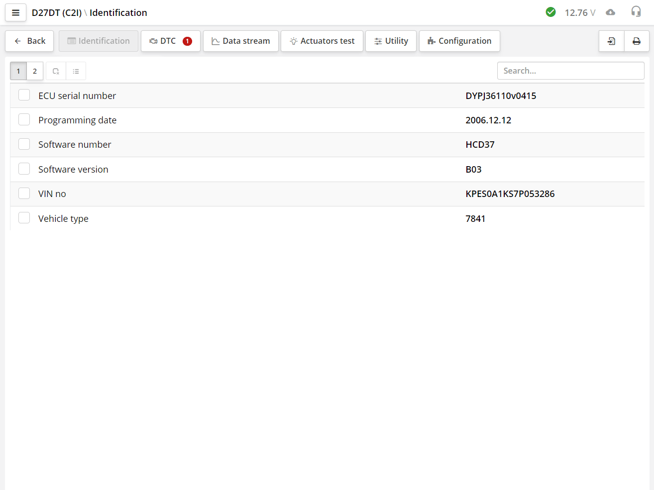
In the identification section, you can see the passport data of the control unit. This data is necessary to determine the software and hardware version, the calibration version of the control units. The identification data also contains additional information necessary for the correct diagnosis of this control unit.
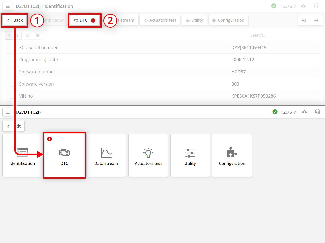
To go to the next bookmark:
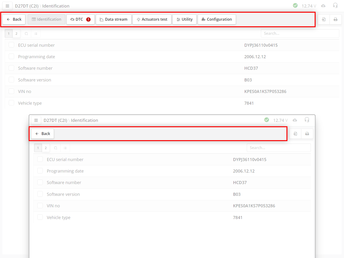
The bookmark buttons will be hidden if the screen resolution is not enough to display them in one line.
The fault codes section displays error codes (DTCs) stored by the electronic control unit, their status and interpretation.
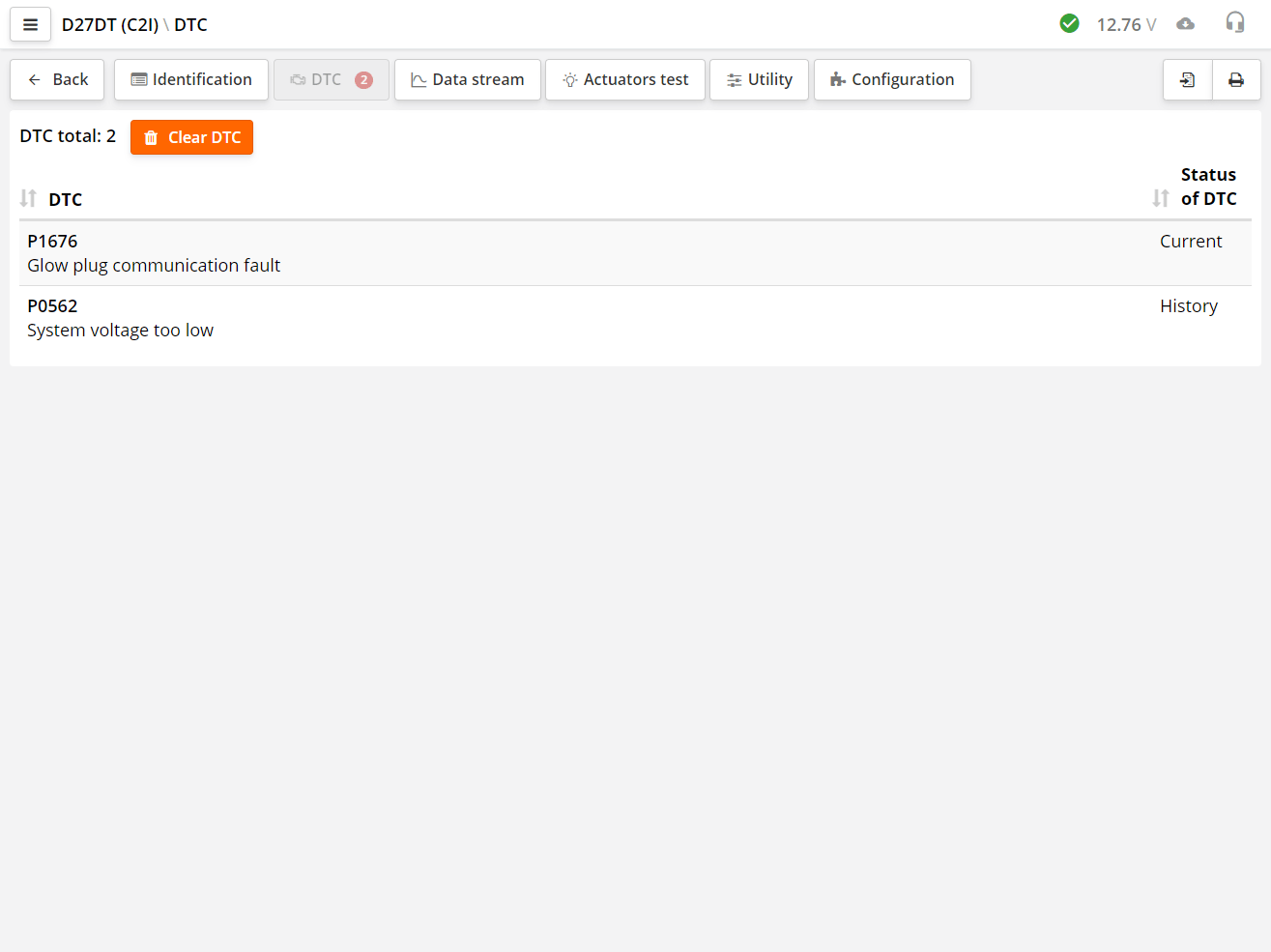
Most ECUs, in addition to storing the error number, can show the current error status in an additional column. Statuses show additional information on the code. For example, that the code is active or was, but is not available at the moment.
The scanner reads the error code and decodes it. The error can be numbered either by the manufacturer or by the OBD-II standard.
To send a command to clear DTCs from the ECU, press the Clear DTC button
The OBD-II standard also provides for codes defined by the manufacturer. These codes start with P1000.
Errors defined by the OBD-II standard
| Symbol | Decryption |
|---|---|
| P | P - Engine (Powertrain) B - Body C - (Chassis) U - Communication. |
| 0 | 0 - Codes defined by OBD-II standard 1 - The codes are defined by the manufacturer. |
| 1 | Vehicle system or component code. |
Some manufacturer's standards assume only a numerical value for the error.
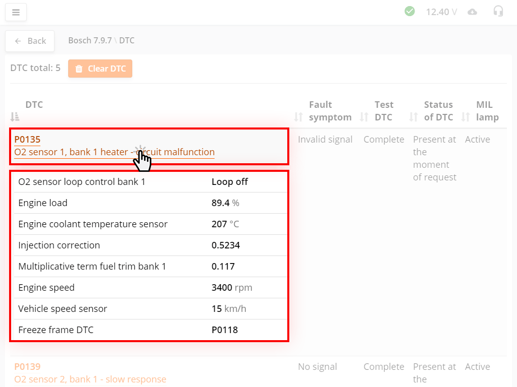
Some units support Freeze frame mode. When an error occurs, information about certain parameters is written to the memory of the control unit. This allows you to determine the conditions under which the error occurred. Freeze frame is recorded separately for each error.
If there is a Freeze frame for the error, then the name of the error is displayed in orange font as a link. To obtain information, left-click on the name of the error. Freeze frame will be displayed below the error.
Some ECUs provide multiple Freeze frames for the same error code. Typically, data is stored before, during, and after the occurrence of the DTC.
If there is no decryption for the error code, then you should contact technical support.
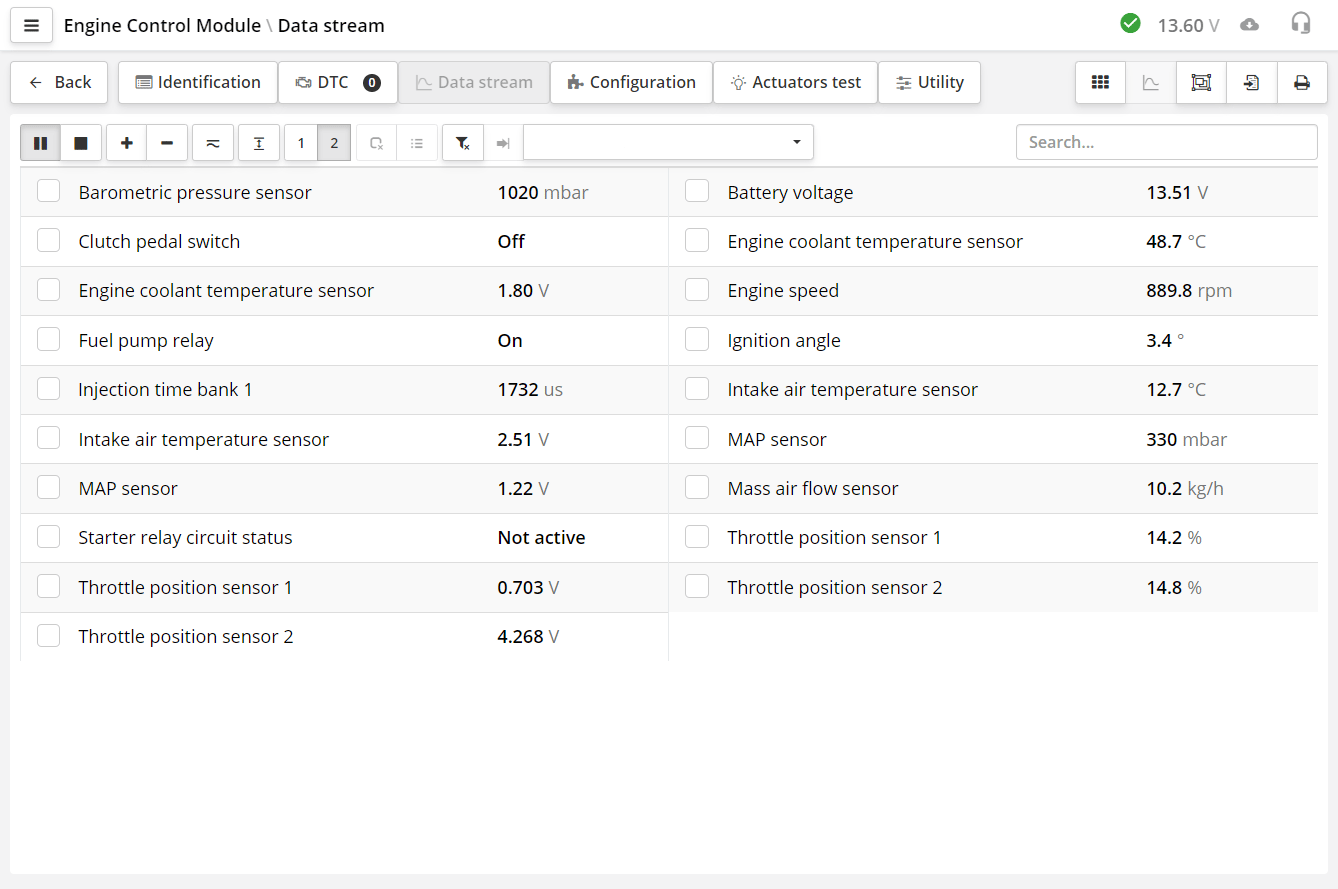
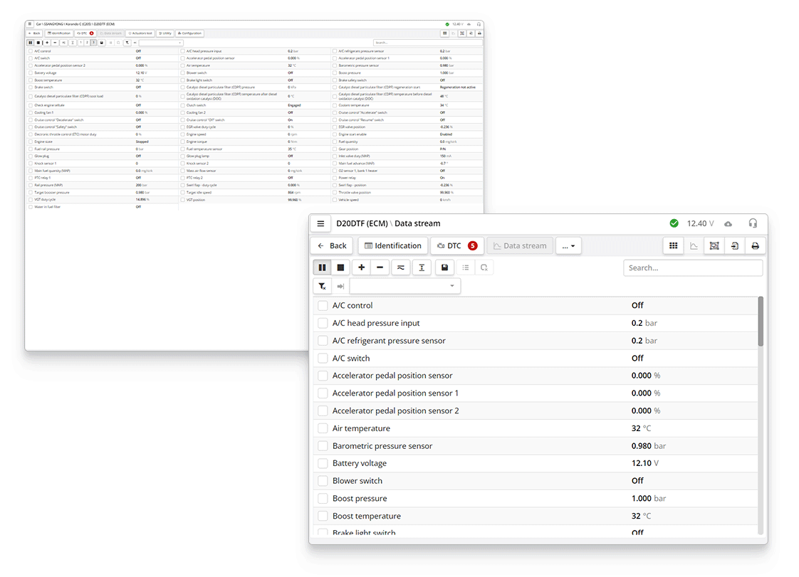
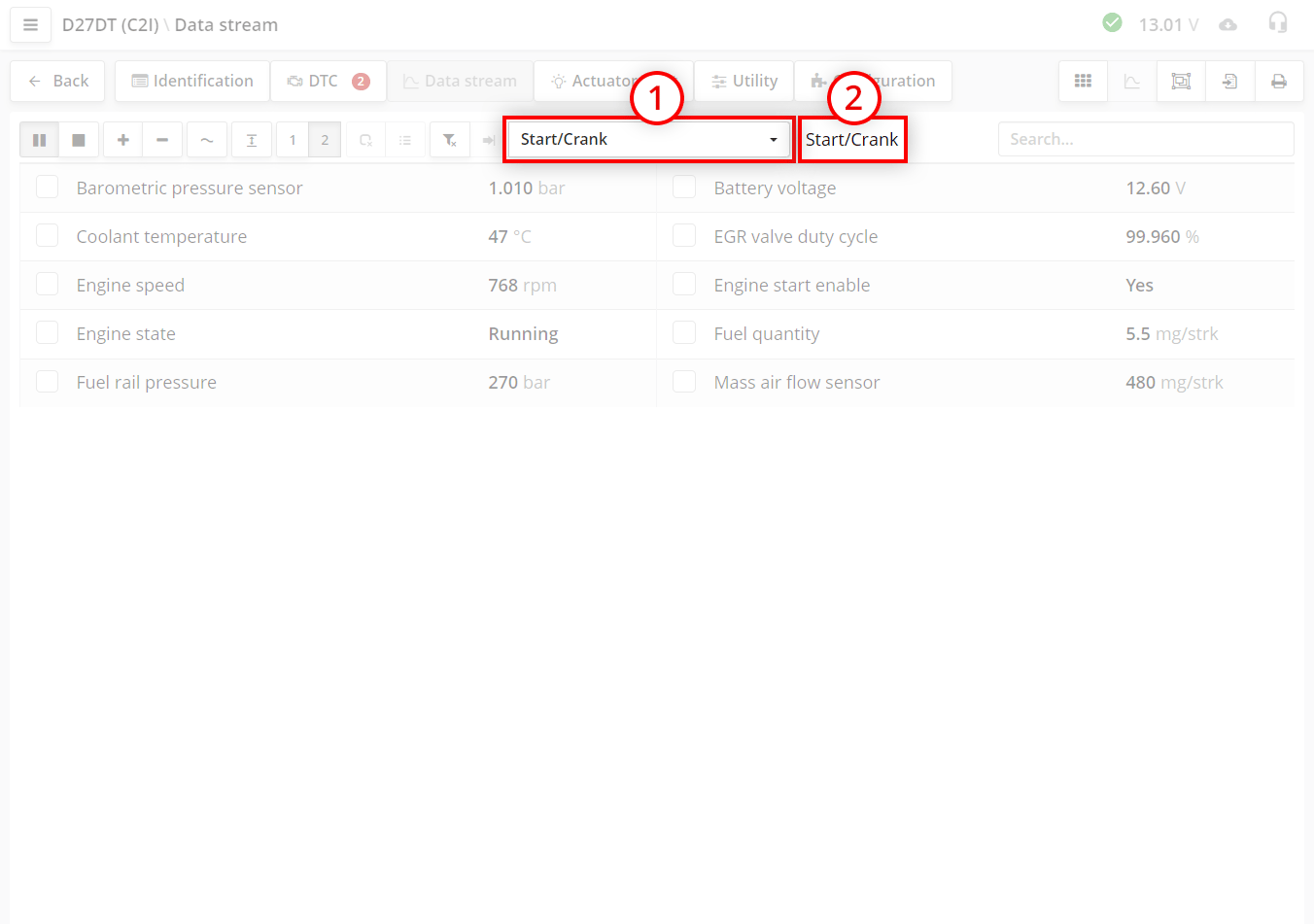
In the "Data stream" section, you can view the current information, read, actuators or status data that are requested from the control unit in real time. The parameter has a name, a value, and, if necessary, a unit of measurement.
Parameters, values and units are displayed here.
The list of parameters can be scrolled with your finger or the mouse wheel. At the same time, please note that only the data that you see on the screen is requested from the control unit. And after scrolling, it may take some slight time for the data to appear. This time depends on how fast the control unit can send data.
In ECUs that work according to the ISO-9141, KW71, KW-1284 protocols, each diagnostic parameter is requested by the scanner separately. Each request takes about 0.1 seconds. Therefore, it will take about 1 second to display 10 parameters on the screen. The more parameters that are displayed on the screen, the longer it will take to update the screen.
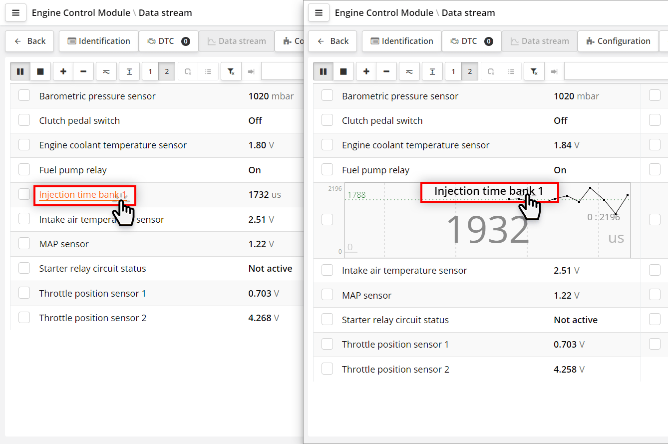
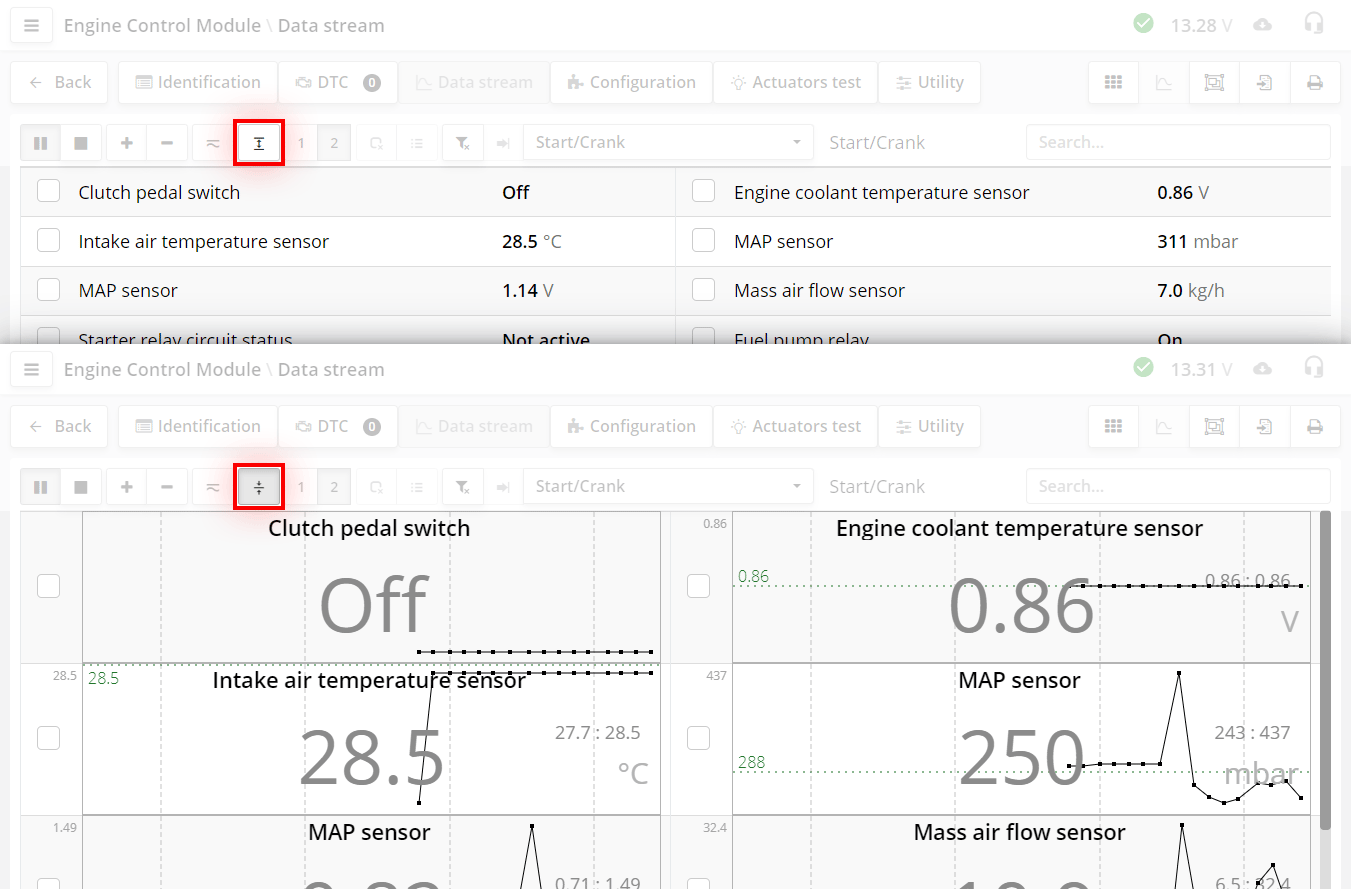
Click on the name of the parameter, you will see the parameter in the form of a graph. If you click again on the name, the parameter will be displayed in digital form.
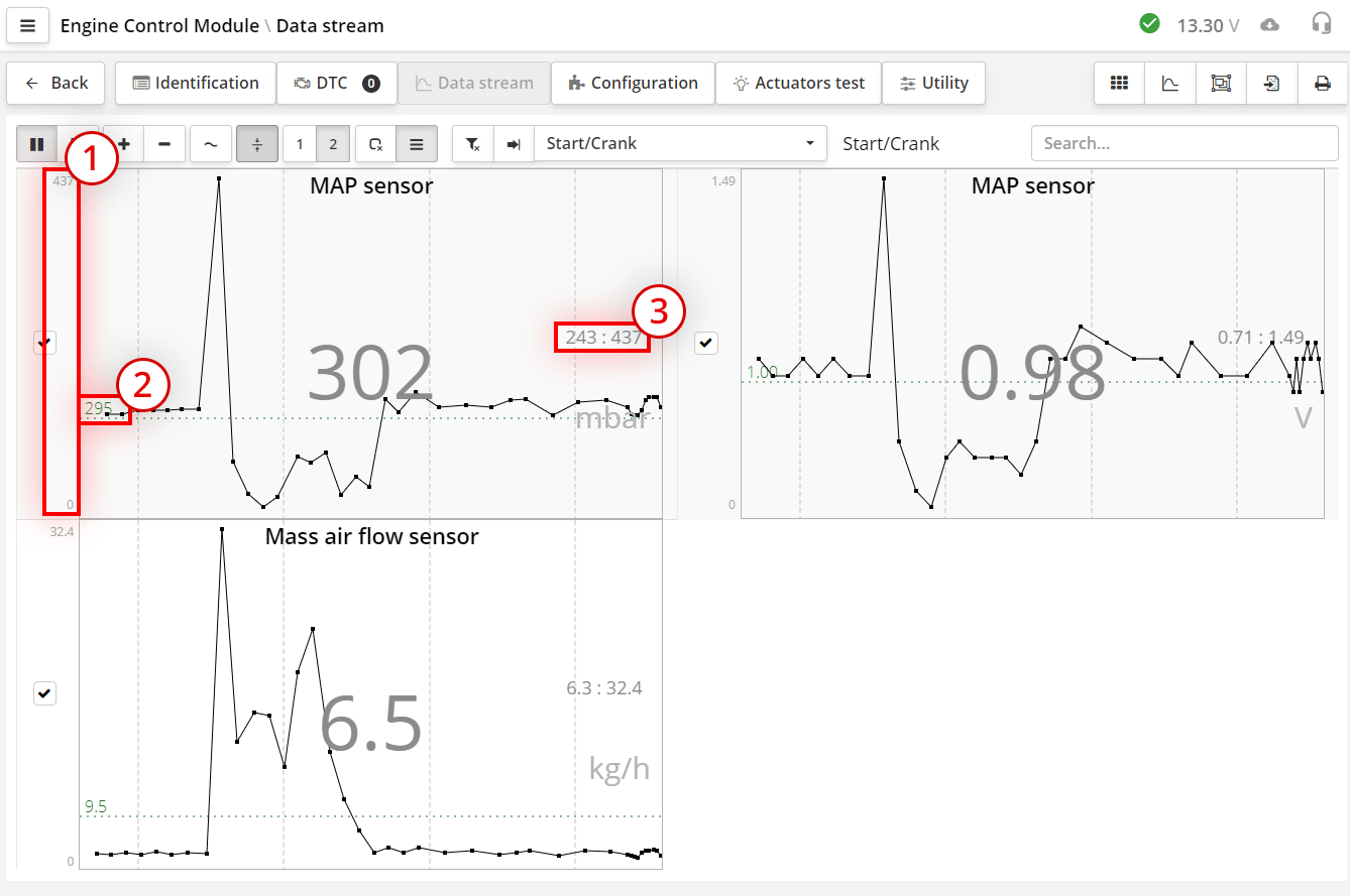
In addition to the name and values, the graph shows:
If there are few charts on the screen, they will be stretched to the full height of the screen. If there are many, then the graphs will be of a fixed size and you can scroll through them.
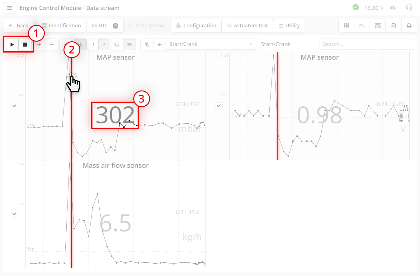
The difference between the "pause" button and the "stop" button is that if you continue reading after the pause mode, the previous data will remain, and after the stop button, the graph will be cleared. Pause mode is needed when you want to see a few fast-moving moments in the background of a lot of time. You stopped at some point, and then you know that for a long time you will not have the information you are interested in. Press pause, and before the right moment, start reading again. The graph saves 1000 readings. For a fast-paced schedule, this is approximately 3 minutes of recording.
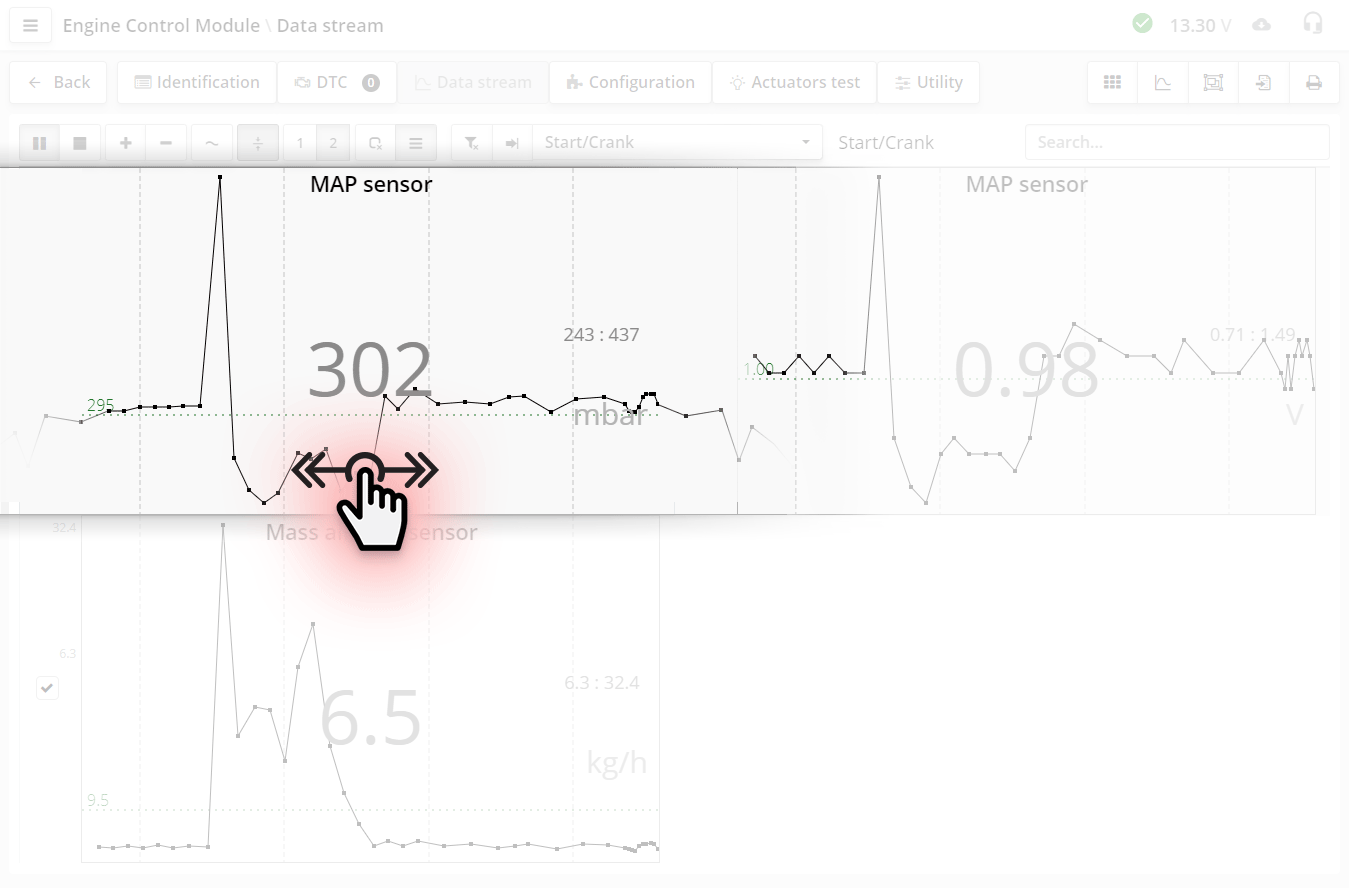
By swiping or dragging the graph with the left mouse button held down, you can scroll the graph horizontally.
In stop mode, data is not read from the control unit. To continue reading the parameters, press the button .
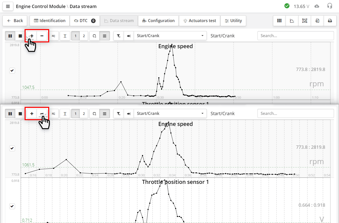
Buttons (plus) and (minus) - change the time scale.
Each press of the button increases
or decreases the time by half. The scale you choose is automatically saved in the program settings. The next time you start the program, the last selected scale will be set.
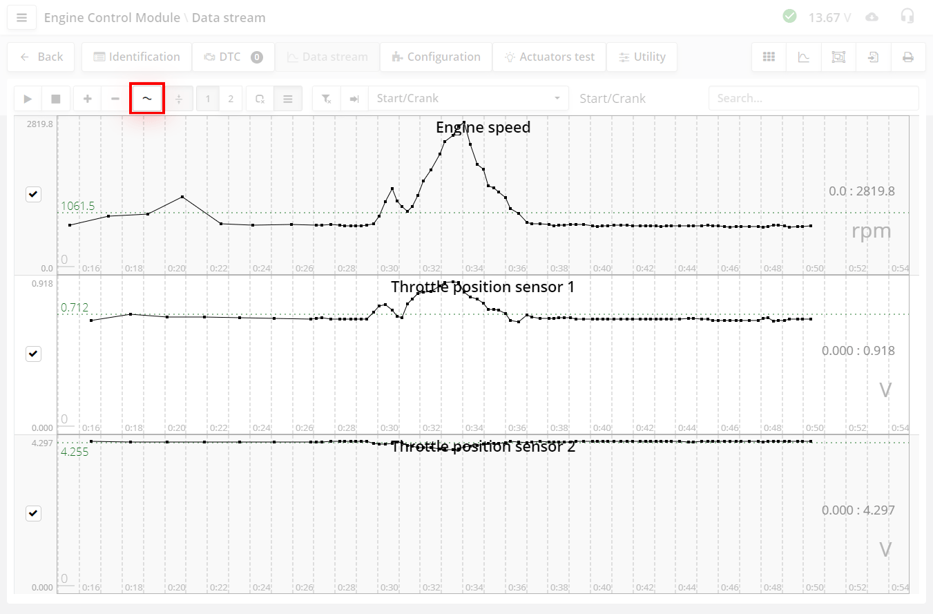
The first mode is called open entry mode.
This is a mode with automatic vertical scaling. In this mode, the program automatically calculates the scale in such a way that the visible part of the graph occupies the entire space in height, starting from the minimum value of the graph
or from the zero line. So, you see the entire range of chart changes in the most detail. This is the main and frequently used mode of working with charts.
But you need to take into account one nuance. Since autozoom constantly
adjusts to the current visible values of the graph, you may not see what you expect. Here is an example of recording from wheel sensors during braking. The car stops, the speed graphs go down, and just before the stop, you see that
the graph goes up. This can be confusing. This happened because at this moment the scale of the graph has increased, and it already shows a range of very small changes in speed. According to this advice. If you want to watch the current
changes slowly, then either set a larger time scale or just pay attention to what range is currently set vertically.
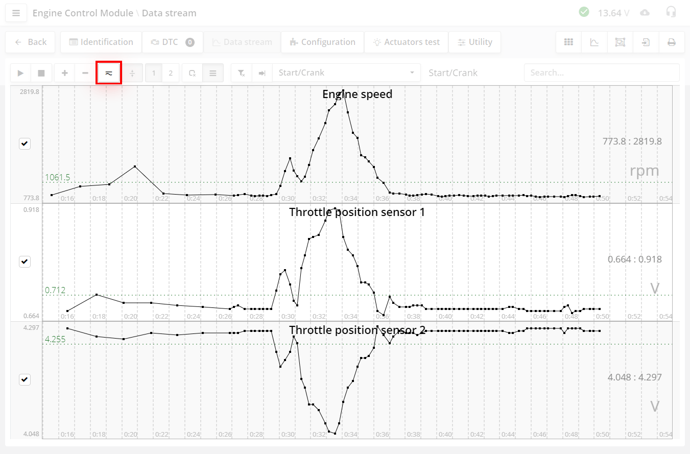
The second mode is called Closed Entry Mode.
This is also a mode with automatic vertical scaling. It works in the same way, but unlike the previous one, here the scale is set not from the zero line, but from the minimum to the maximum of the chart. This means that the constant component of the graph is cut out. This mode is needed when you want to see slight fluctuations in the chart against the background of a large constant shift. For example, you want to see fluctuations of a few atmospheres against a constant displacement of a hundred atmospheres.
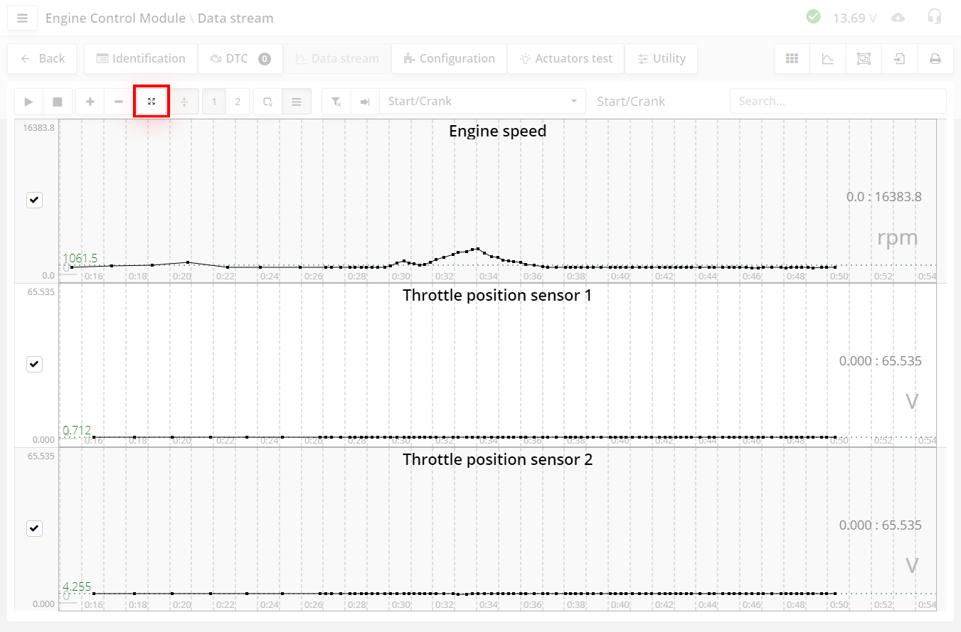
Third mode. This is normal mode without autoscale.
The graph is shown in the entire possible range of the parameter. The range of the graph change is not always set by the manufacturer, and then the range is taken from the maximum value of the number. These values can be very large, and then you may not see the change in the graph.
Select the display mode depending on the situation.
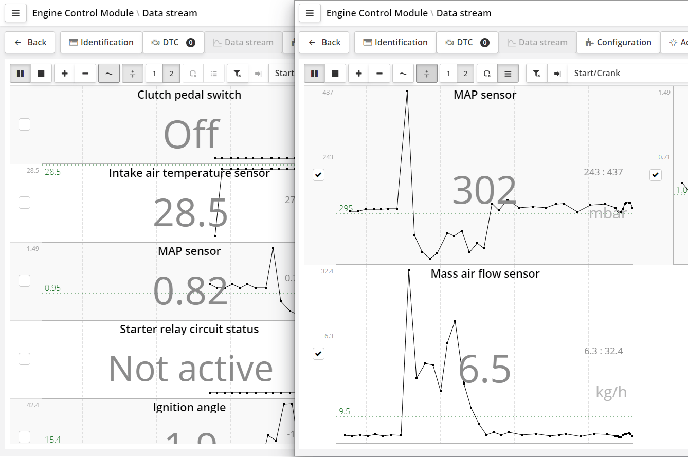
- button to show all parameters in the form of graphs or digital form.
If there are a lot of parameters, then depending on the power of the computer, there may be a slight delay in response.
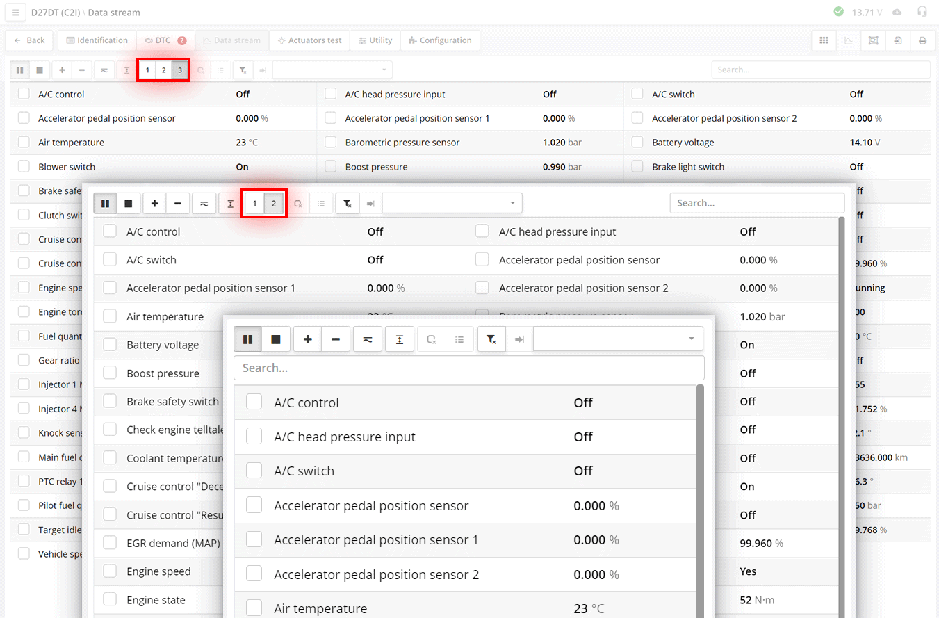
123 - Options for displaying parameters.
You can select 1, 2 or 3 columns. Depending on the screen resolution, these buttons are hidden by
(for example, only one column will be shown on a mobile phone screen).
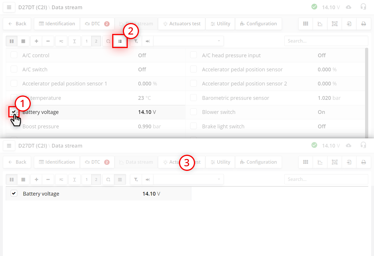
Each parameter has a parameter selection checkbox on the left
By setting it we mark the parameters for further work.
It is necessary when you want to get the maximum display speed of the parameter and see its fast changes. The more parameters you see on the screen, the slower they appear. Therefore, if you need to watch fast changes, choose fewer parameters.
Another press of the select button returns to normal mode
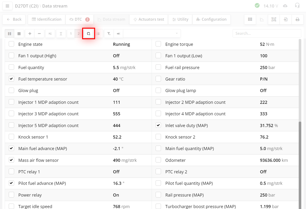
The button deselects all parameters.
This is convenient when there are a lot of parameters and you have marked them in different places. And in order not to search for them throughout the list, you can simply click this button.

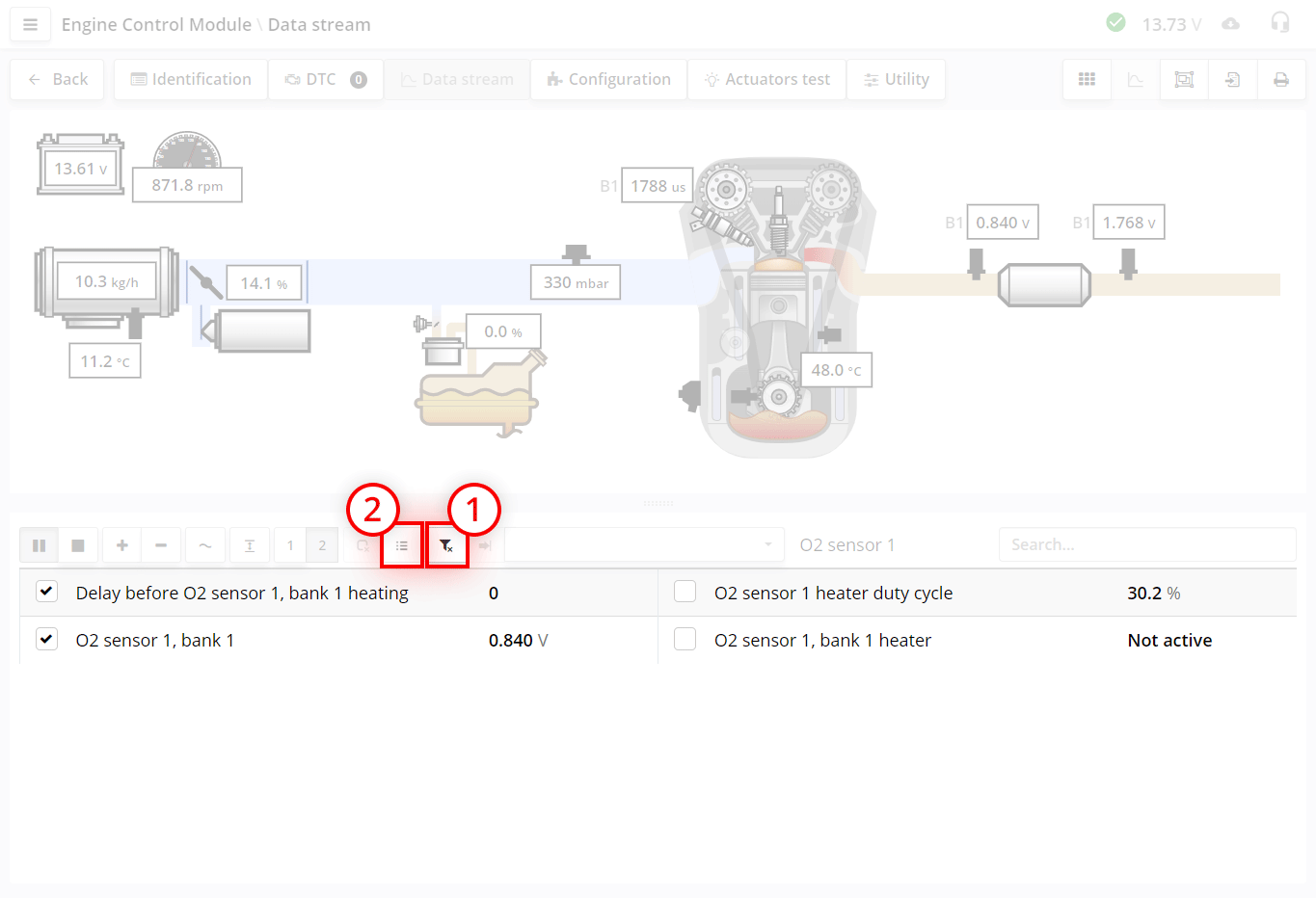
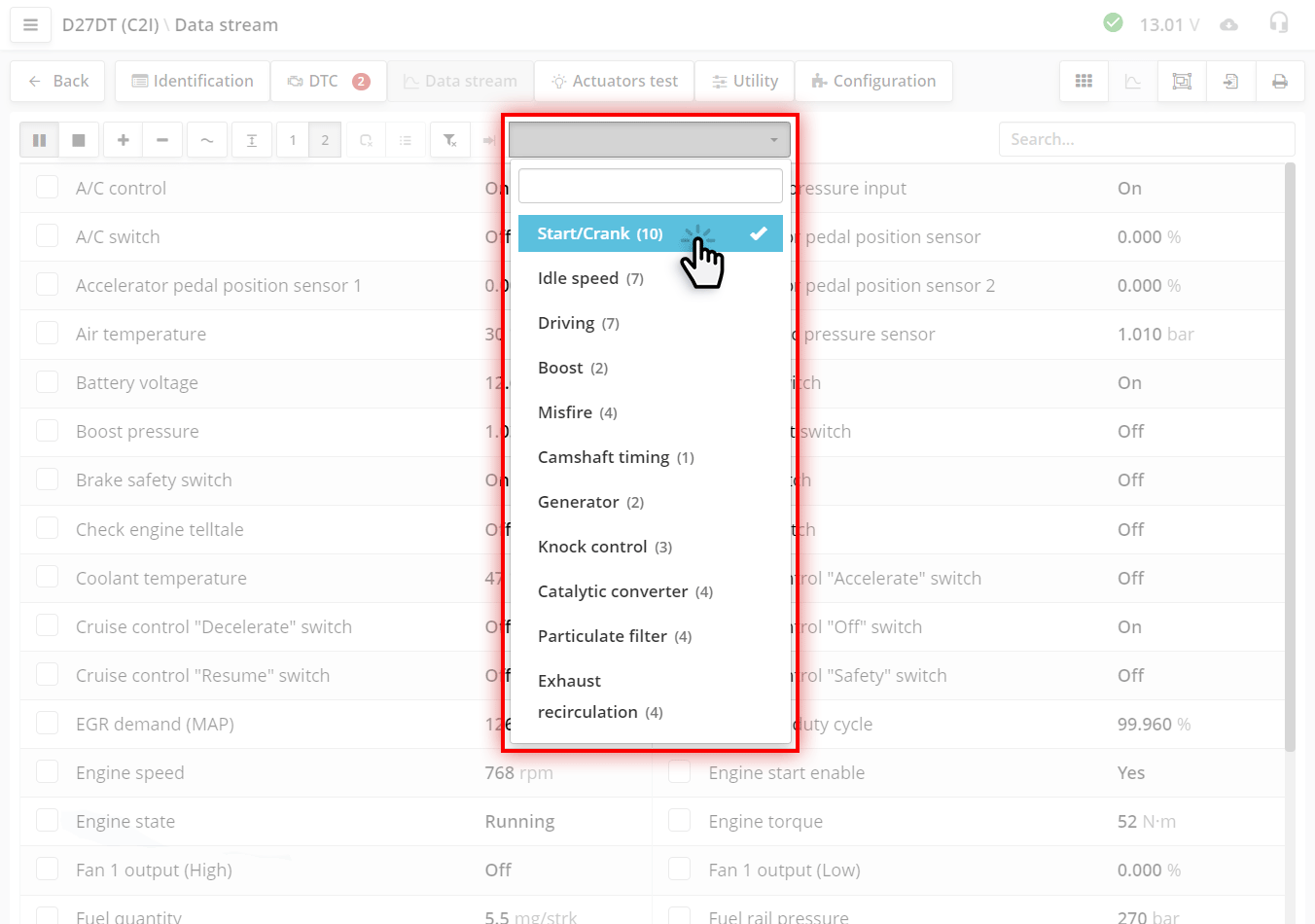
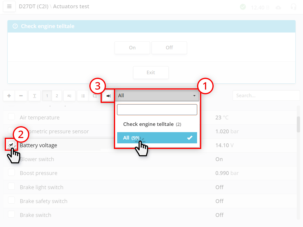
The dropdown list is a filter selection.
For more details, see the Working with filters section.
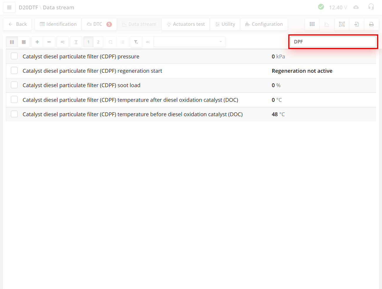
Search bar.
If you need to show only those parameters in which a specific word or abbreviation is mentioned, for example "DPF", start writing it in the search bar, as you type, parameters will be selected in the name of which the word "DPF" is present.
To cancel the selection of options, delete all text in the search bar.
The selection is carried out by all subtracted parameters, even if they are not shown on the screen.
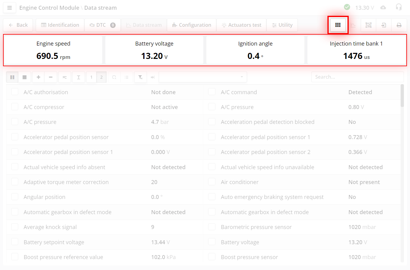
- indicator button.
Indicators are fixed parameters that are used most often. Indicators are needed for a quick assessment of the main parameters.
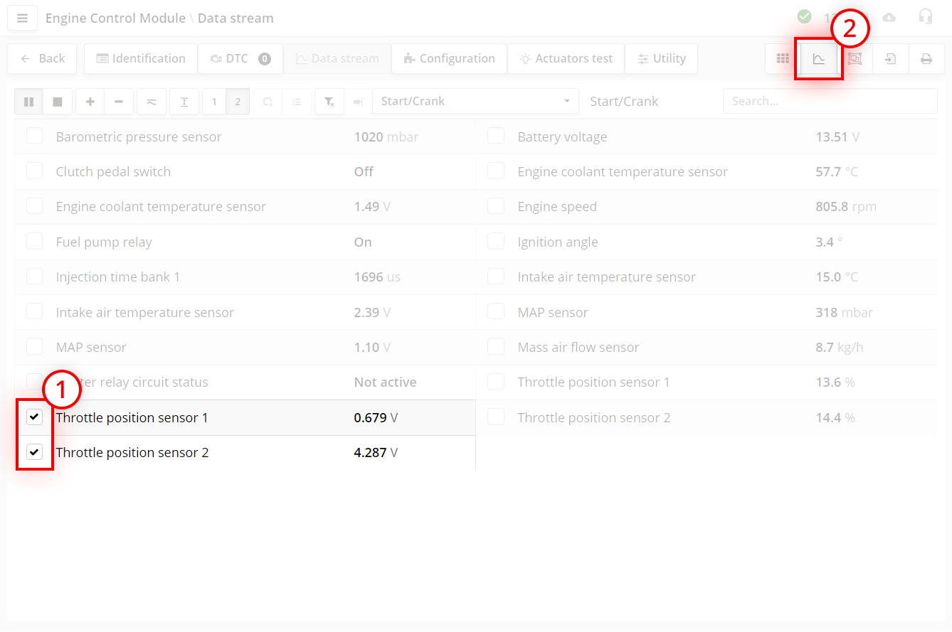
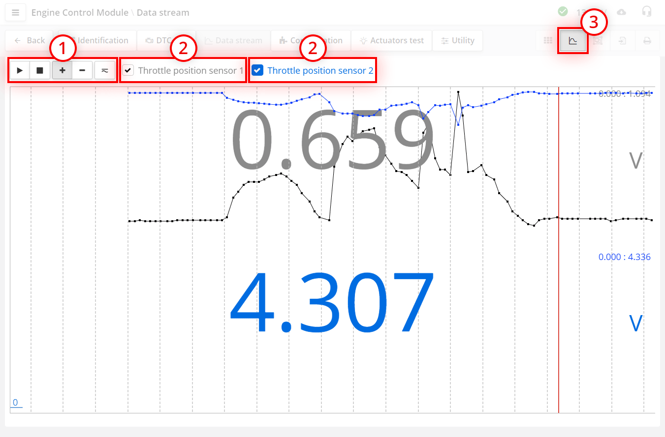
- button for chart overlay mode.
This mode is needed to view related parameters. For example when viewing throttle position sensors. This mode is activated when there are checked parameters. The graph can show from one to 4 parameters.
It works like this:
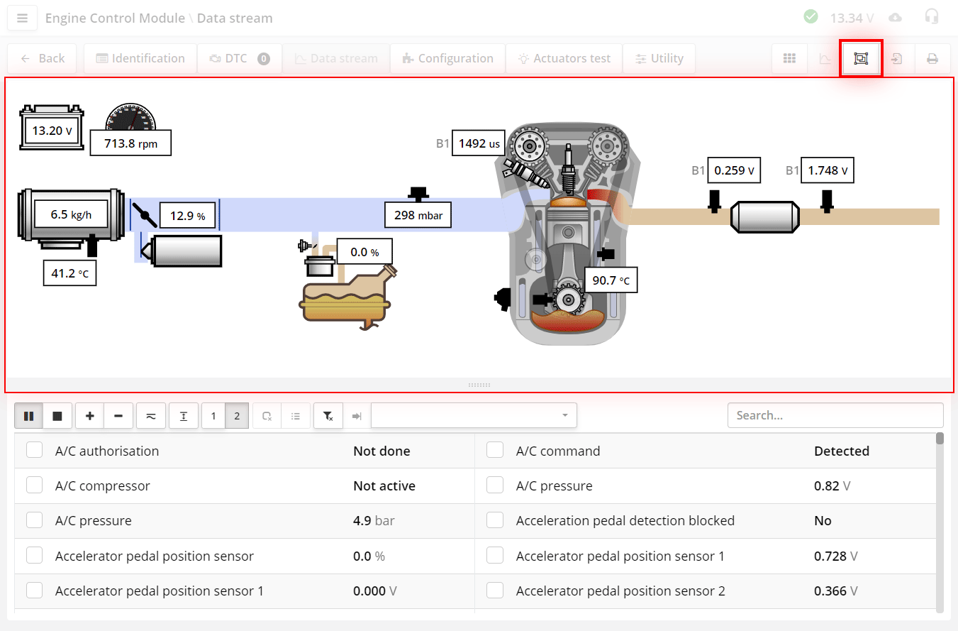
- the button turns on the "schematic" mode.
The diagram shows which components are installed in the system and the meaning of key parameters.
The scheme for each control block is built automatically based on the names of the parameters that are present in the control block. It is needed so that you can quickly assess what is in the system. For example, how many lambda sensors. Is an air mass meter or intake manifold absolute pressure sensor, etc. installed.
The circuit is also needed in order to quickly find the parameters of these components.
The scheme is not present on all devices.
The scheme cannot be enabled on smartphones, this is due to the small screen size.
The appearance of the program, set in the settings, also does not affect the display of the scheme.
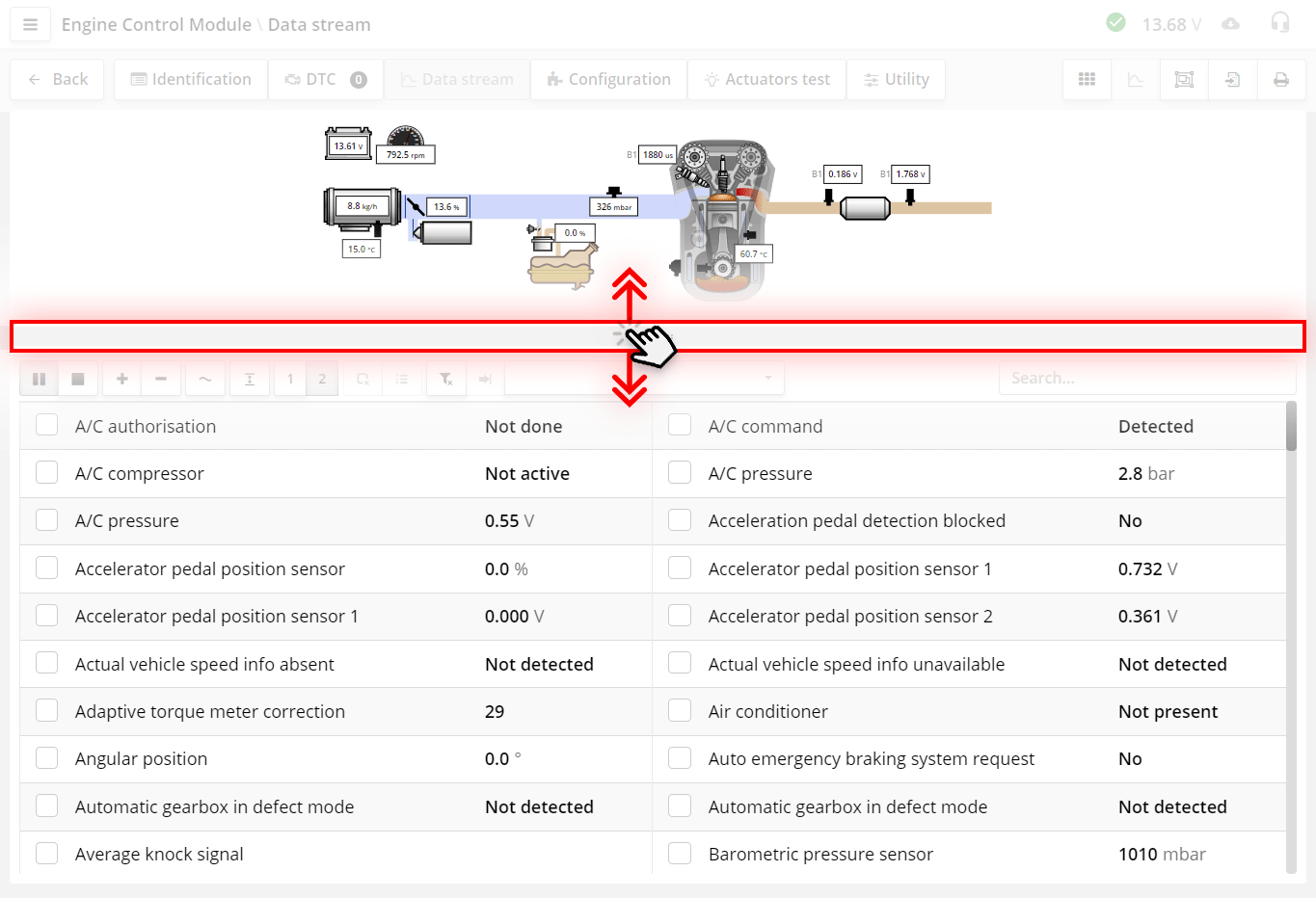
To resize the scheme, drag the slider. This is convenient if the circuit is large and few parameters fit on the screen.
The size of the scheme is saved in the browser settings and the next time you open the diagram, it will be the same size as you set last time.
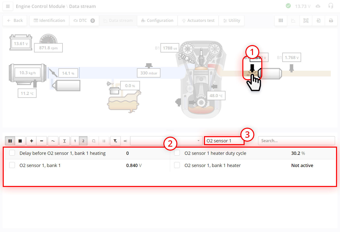
In essence, the scheme is a set of filters.
By clicking on the various components of the circuit, we can find the desired parameters. If we want to collect parameters from different systems, then we can mark these parameters by checking the checkboxes.
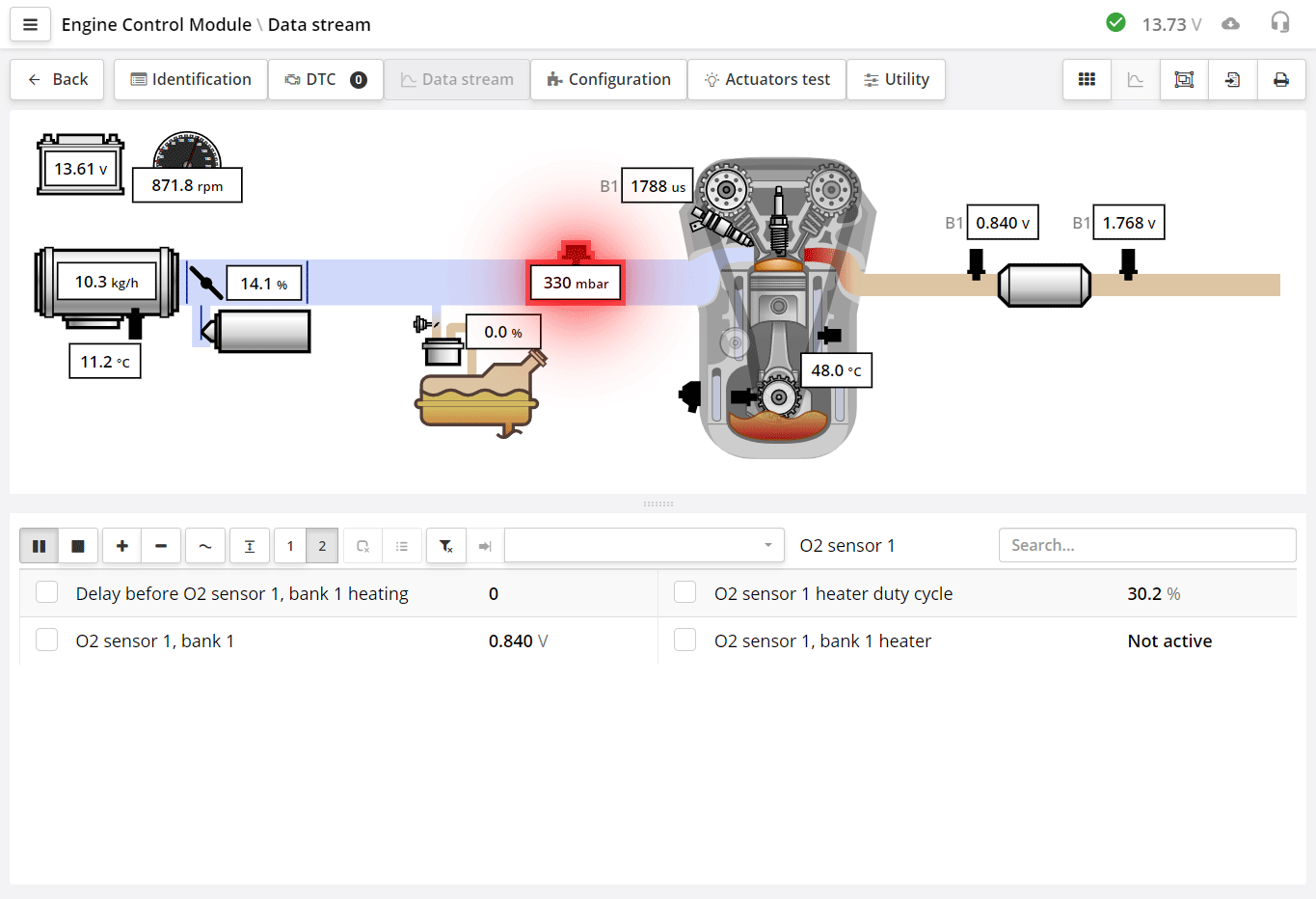
If a DTC is stored for a component in the control unit, the component will be highlighted in red flashing.
If you see a system in the diagram that is not really present in the machine, this does not mean an error. Some control units are created as universal for a group of motors. Their set of parameters may contain systems that are not available in a particular motor.
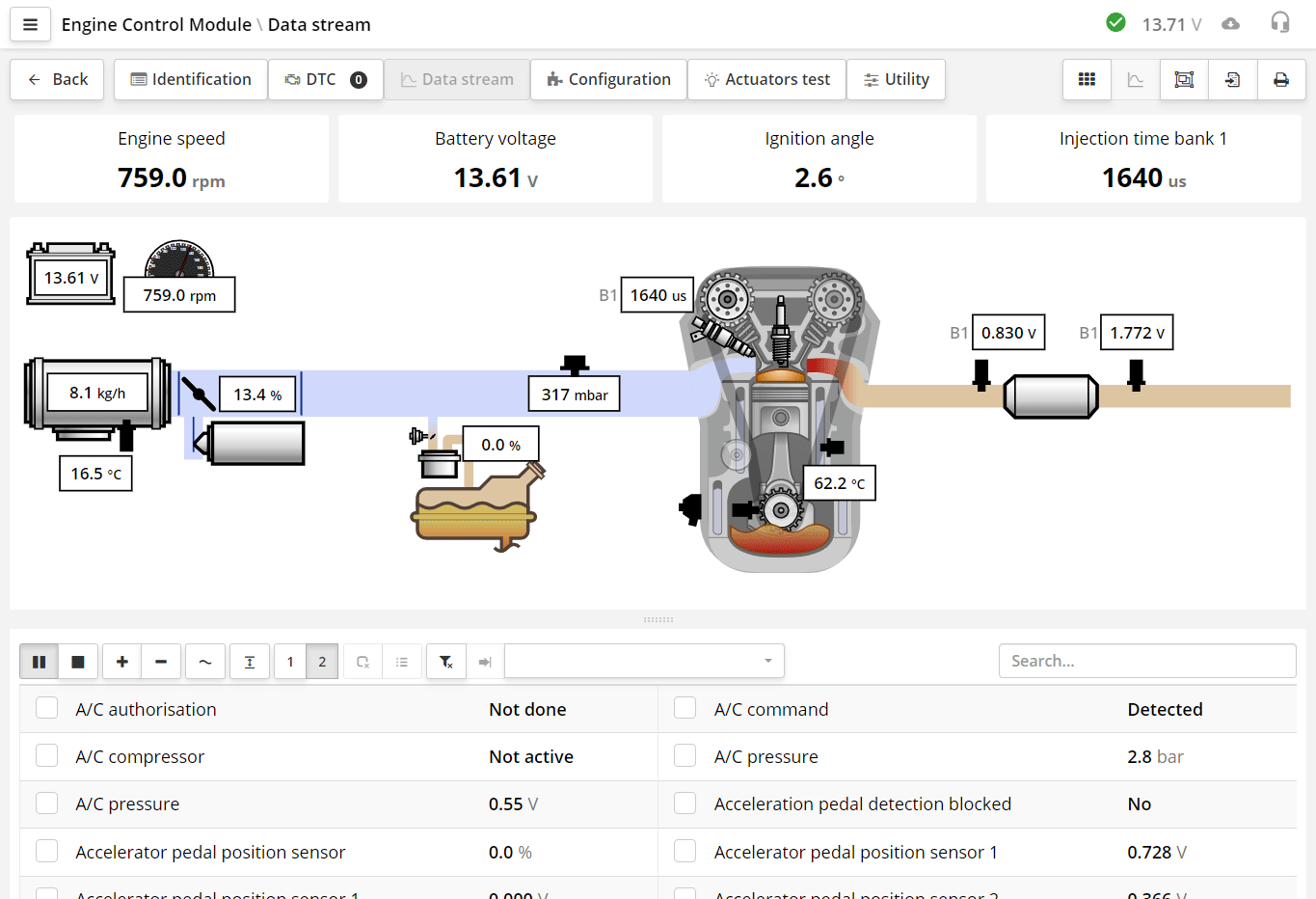
The chart and indicators can be opened at the same time.
When you decide to look at some data, you already know exactly what parameters you want to see, but you don't know if they are in this particular ECU.
The set of parameters you want to see depends on the specific situation and the type of fault. For example, if the car does not start, then the probable causes may be: a crankshaft sensor that is not working, an immobilizer blocking the start, or something else. In order to localize the cause, you need to see certain parameters that may be associated with this defect. For example: engine speed, crankshaft timing, injection time, immobilizer status and something else.
On the "data stream" tab, you can filter only the parameters you need by creating your own set of filters. Filter sets are needed to quickly display the parameters you have chosen in advance.
If the car is misfiring, then you need to see RPM parameters, misfire parameters, ignition timing, etc. Thus, for each case, you have a certain set. In order not to look for these parameters every time, for each case, you can add them to the filter once and simply select the desired filter when necessary.
In fact, the filter is your technique, not a set of parameters for a particular block. Using the filter, in two clicks you get a list of the necessary parameters for a particular case.
When installing the program, we offer a basic set of filters. We deliberately did not make a complete list, because diagnosticians have individual methods, and it is easier to add to the filter than to remove from it. You can delete them, create your own or edit them. You can do this in the settings.
We recommend that you, before starting all the work, calmly, once, decide which filters you need and create them. You don't have to fill them up right away. Then, during operation, you can enter parameters for troubleshooting by adding them to the desired filter.
Work with filters is carried out in the program settings window.
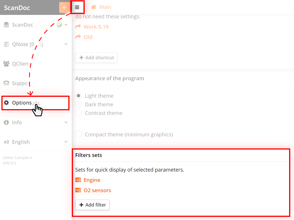
Click on the button at the top of the window, an additional side menu will appear.
Click on the "Options" button in the side menu, you will be taken to the program settings window.
At the end of the list of settings there will be an item "Filter sets".
To create a new filter, click the Add Filter button.
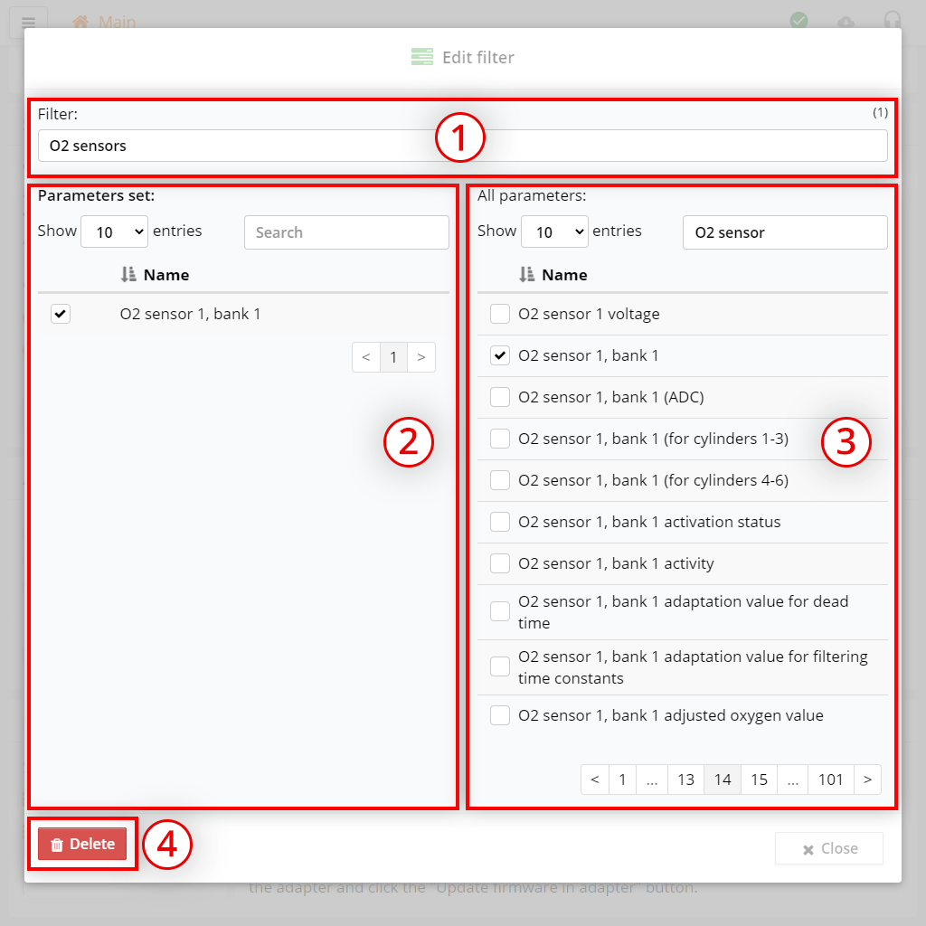
The filter editing window will appear:
How to quickly create a set of your parameters:
If you need to remove a parameter from your filter, uncheck this parameter in the left table.
The filter is saved automatically, after editing the list of parameters, just press the button Cancel
You can apply the filter in the "datastream" tab.
Above the list of parameters in the data stream, you can see a drop-down list with filters.
Click on the name of a filter to apply it to the current list of options.
If the parameters that are in the filter are not in the current ECU, then the filter name will not appear in the drop-down list.
If you apply a filter, then only those parameters that are in the filter and are present in the ECU will be displayed.
To cancel the filter and show all parameters from the ECU again, press the (clear filter) button.
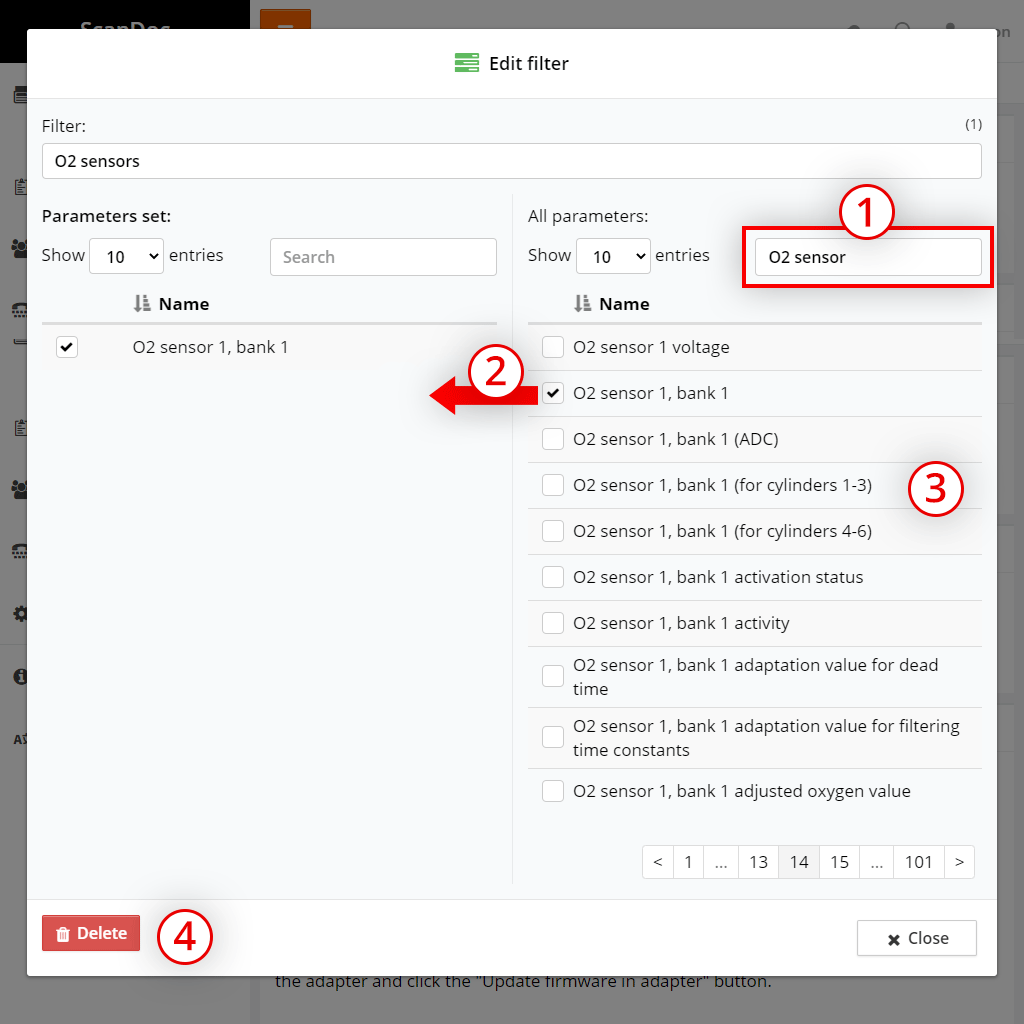
If in the course of work you saw a parameter that you forgot to add to the filter, then you can quickly add it without interrupting your work.
You can quickly add a parameter only to a previously created filter.

To quickly add a parameter to a previously created filter:
The options you selected will now be in the filter.
Parameters that are the same or close in meaning can be named differently in different control units.
Add parameters to the filter while working and after a while your filter will accumulate all possible combinations of the necessary parameters and you will very rarely add new parameters. Do not worry that the filter has something that is not present in this block. The program will show only those parameters that the filter will contain hundreds of similar parameters. The main thing is that they are needed for this case.
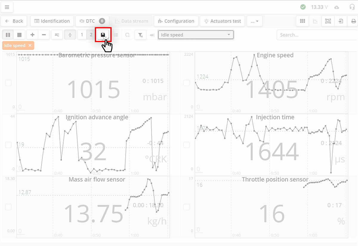
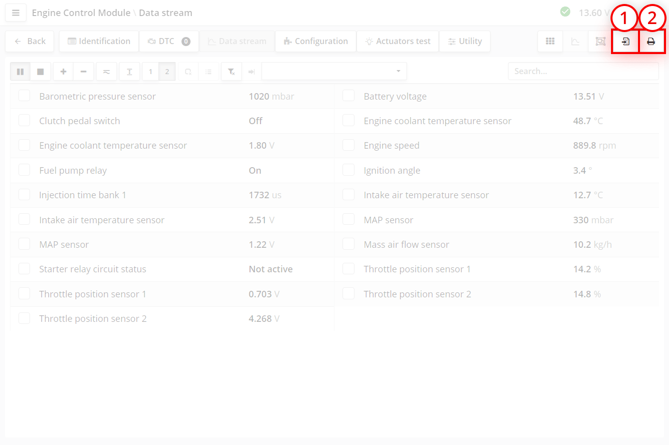
You can save the data stream. To do this in the data stream window, click the button.
The data will be saved to the Clients program on the current device.
You will see an alert in the upper right corner of the program when the save is successful.
Many control units allow you to temporarily control actuators (injectors, motors, solenoid valves) to check their performance.
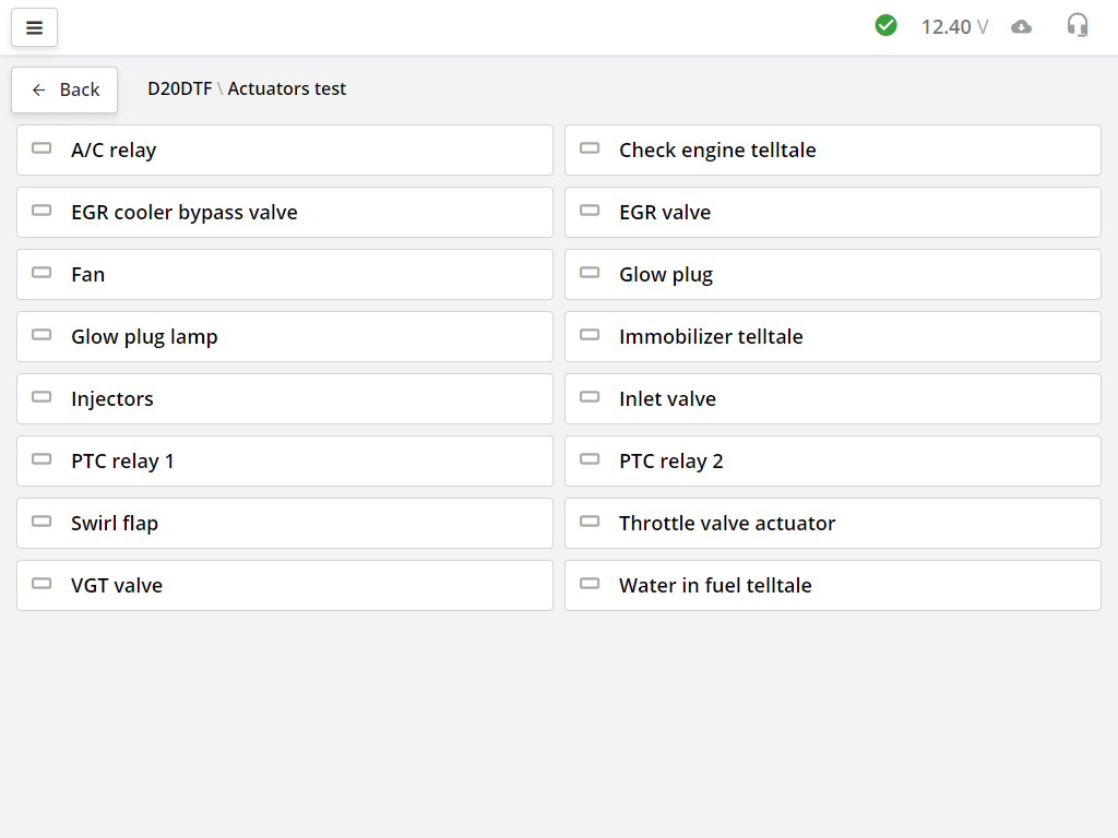
The list of actuator tests depends on the specific ECU model.
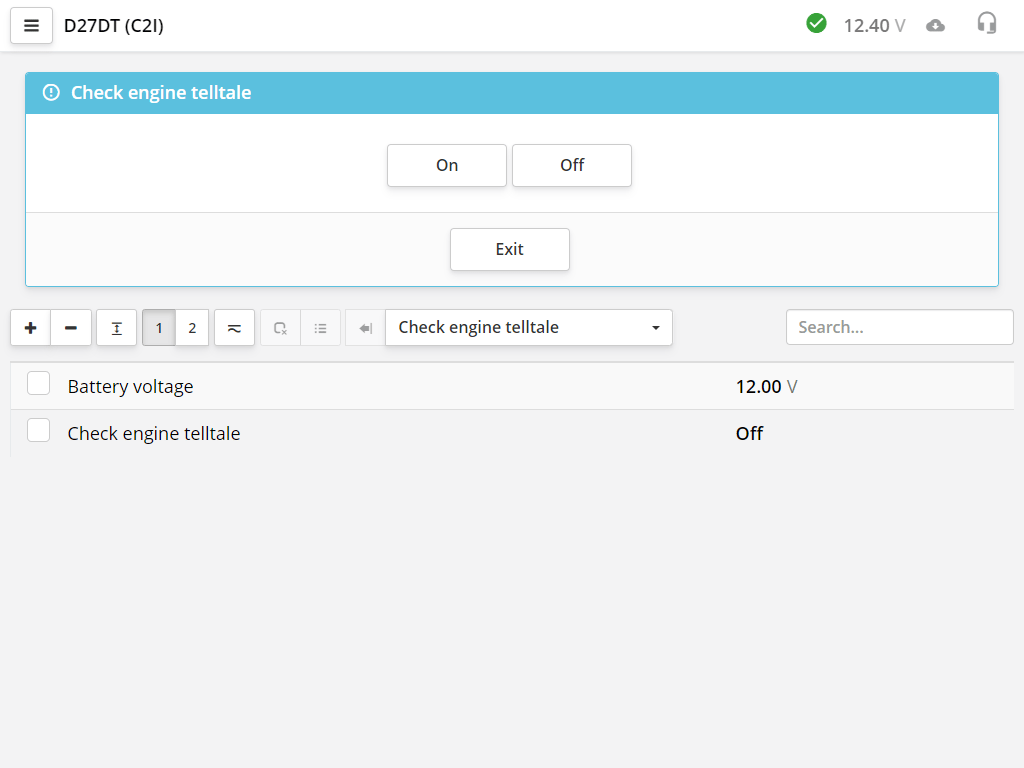
Select an actuator, you can control it using buttons or knobs. Sometimes, for convenience, the current readings of some parameters are displayed. Each actuator is tested in its own way.
Often additional parameters need to be monitored. For each test, a filter is provided. If there are parameters for it, then it turns on automatically.
If some parameters are missing, then you can add them yourself:
There are brands that do not allow you to run tests against the background of data flow. For example, the VAG group, so there will be tests only with the data flow that the manufacturer has provided.
This section contains specialized functions of the ECU, such as adaptations, resets, etc.
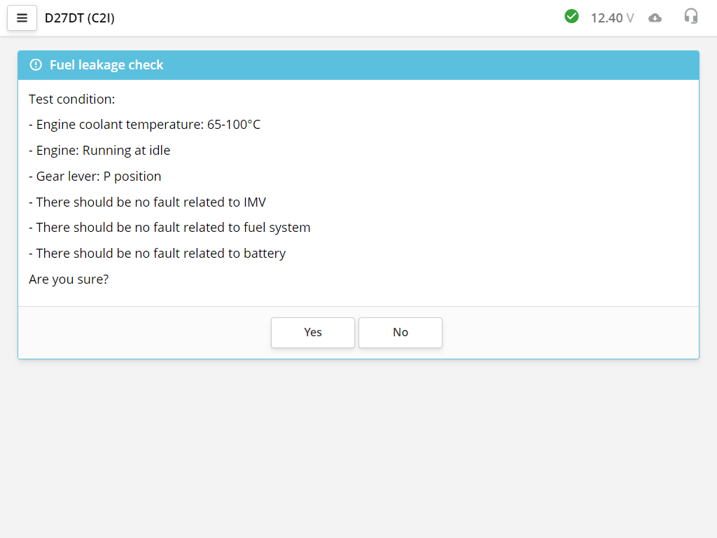
Utilities are also launched by clicking on the tile with its name. Read the description carefully, if any, and follow the conditions of the ulilith.
Whatever function you run. The first window will always be informational. Running the test utility or coding will never start the procedure as the first step. Therefore, you can safely run the utility and read its description.
Some components of the vehicle systems, after installing new parts, or periodically, require an adaptation procedure. This can be, for example, teaching the control unit the extreme values of the throttle sensor or the clutch pedal.
The engine management system adapts to changes in sensor parameters. When installing new spare parts, resetting previously saved corrections is required. To do this, you need to reset the adaptations.
It is done when changing the oil. The reset procedure varies from manufacturer to manufacturer. In one case, it may be just one reset button, in the other - programming the run interval until the next warning occurs. For a more detailed description, refer to the vehicle repair documentation.
To reduce the number of ECU options and software options produced, ECU manufacturers make universal blocks that are configured for a specific vehicle configuration.
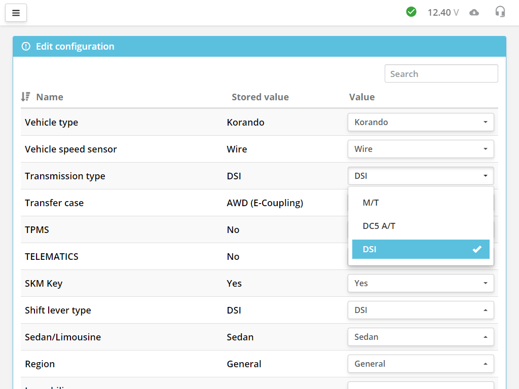
The configuration is also often referred to as coding.
The number of encoding parameters depends on the specific ECU model.
Here you see the name of the parameter, its current state, and the new state that can be changed.
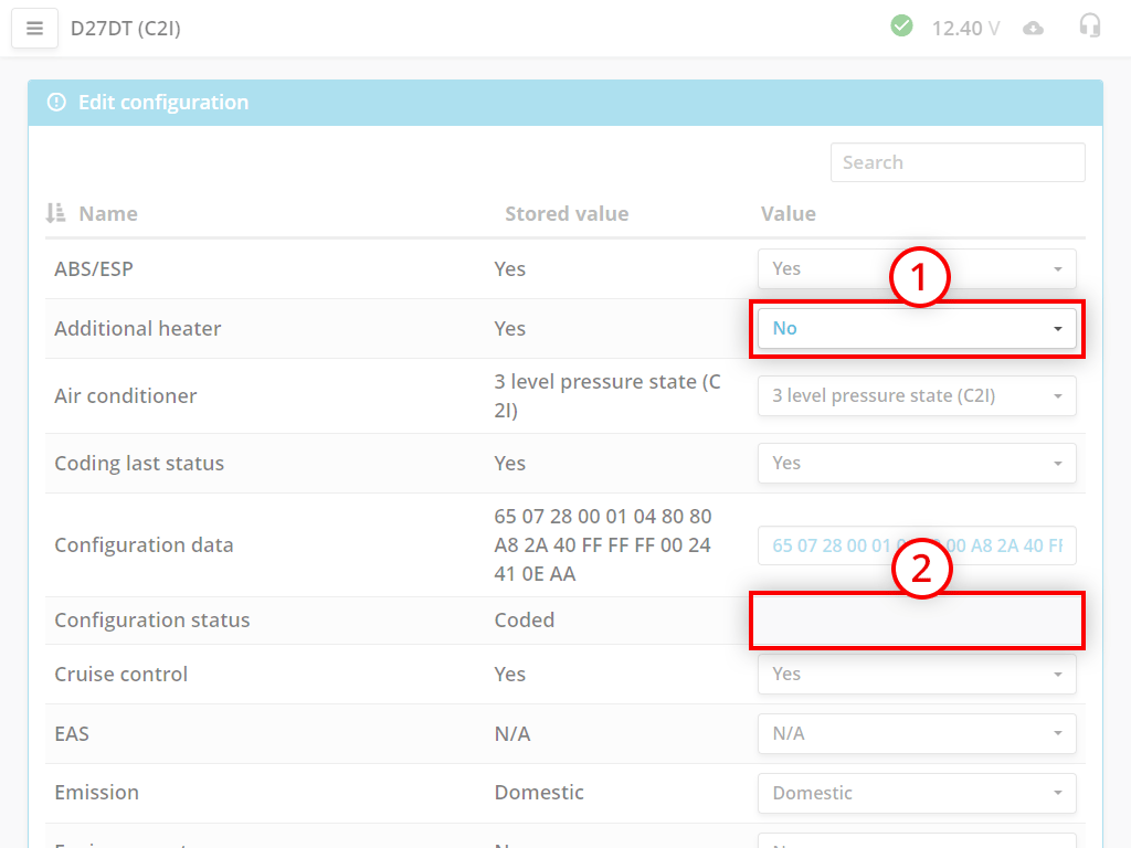
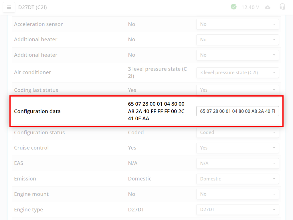
In the options there is a "Configuration Data" option. This is the hex code for the entire configuration. When you make a change to the dropdowns, this code also changes.
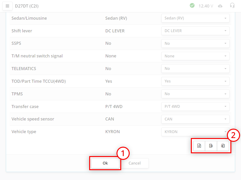
Change the required parameters and click the Ok button, the scanner will write data to the block.
Additional buttons for working with the configuration:
With each entry, the configuration is saved automatically and linked to the internal name of the control unit. Once you've made an entry, you can revert back your changes with the button (History of changes).
You can work either in the old or in the new version of the program. The scanner must have the firmware of the version of the program with which you want to work. Therefore, if you want to upgrade to a different version of the program, you must enter the scanner into download mode and perform a firmware update.
If for some reason the adapter did not update, then you can exit the download mode by turning off and on the power of the device
Now you need to update the firmware on the device.
If for some reason the adapter did not update, then you can exit the download mode by turning off and on the power of the device
Now you need to update the firmware on the device.
Connect the scanner to the computer, run the ScanDoc program.
The scanner is ready to work with the old program!
The scanner is ready to work with the old program!